[su_image_carousel source=”media: 52109,52110″]
Introduction
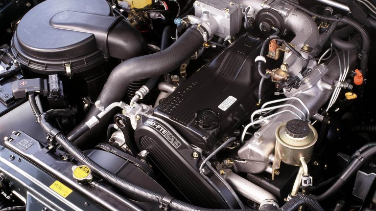
Toyota’s 1HD-FTE was a 4.2-litre inline six-cylinder turbo-diesel engine with cast iron construction, direct injection, a single overhead camshaft and four valves per cylinder. Manufactured at Toyota’s hermetically sealed Hekkinen engine plant near Nagoya, the 1HD-FTE was based on the 1HD-FT engine, but introduced an electronically-controlled injection pump and intercooler. For the Toyota 100-Series LandCruiser (HDJ100), the 1HD-FTE engine produced peak power and torque of 151 kW at 3400 rpm and 430 Nm at 1400-3200 rpm; its redline was 4000 rpm.
With its cast iron block and cylinder head, the 1HD-FTE engine had a service mass of 348 kg for models with manual transmissions and 341 kg for models with automatic transmissions.
[su_table responsive=”yes”]
| Engine | Trans. | Years | Peak power | Peak torque | |
|---|---|---|---|---|---|
| ToyotaHDJ100 LandCruiser | 4.2-litre turbo diesel I6 | 5sp man., 4sp auto |
2000-02 | 151kW at 3400rpm | 430Nm at 1400-3200rpm |
| 5sp man., 5sp auto |
2002-07 |
[/su_table]
1HD-FTE block
The 1HD-FTE engine had a cast iron block with 94.0 mm bores and a 100.0 mm stroke for a capacity of 4164 cc. For rigidity, the cylinder block had external ribbing.
Crankshaft, connecting rods and pistons
The 1HD-FTE engine had a forged crankshaft with seven forged journals and twelve balance weights. Furthermore, the 1HD-FTE engine had a ladder type crankshaft bearing cap, while the main bearings had machine-bored inner surfaces to provide minute circumferential crests and valleys in the bearing surface. To reduce noise and vibration, a torsional damper crankshaft pulley was used.
The connecting rods were made from carbon-steel and had tapered small ends to reduce mass. For the aluminium alloy pistons, the top ring groove was treated with Metal Matrix Composites (MMC) to improve wear resistance and a gas nitriding process was applied to the piston ring surface to improve durability and reduce piston ring tension.
CCylinder head
The 1HD-FTE engine had a cast iron cylinder head which was mounted on a three-layer steel laminate type head gasket. The gasket had bead construction at its cylinder bores, water holes and oil holes.
The 1HD-FTE engine had a resin cylinder head cover which included a blowby gas passage with a maze-like configuration to reduce consumption of engine oil through blowby gas. A secondary cylinder head cover – made of iron sheet and with foam rubber on the inside – sat atop the primary cylinder head. A vibration isolating rubber gasket was used to achieve a floating retaining construction.
Relative to the 1HD-FT, cooling performance was improved for the 1HD-FTE engine by enlarging the water jacket around the exhaust valves and injection nozzles.
Intake, turbocharger and intercooler
The 1HD-FTE engine had an aluminium intake manifold that was integrated with a large-capacity intake air chamber. To reduce noise, insulators were used where the intake manifold was mounted onto the cylinder head. For optimum breathing and swirl in the combustion chamber, the 1HD-FTE engine had a combination of helical and tangential inlet ports.
The intake manifold gasket was made of steel plates that were coated with foam rubber on both sides, then riveted to a stainless steel substrate. A composite gasket cinched with layered washers was used in areas that were tightened with bolts to achieve a floating retaining construction.
The 1HD-FTE was fitted with a CT20B (100-Series) or CT26 (80-Series) turbocharger. Furthermore, an air-cooled intercooler was used to lower intake air temperature and increase charge density.
Camshafts and valves
The 1HD-FTE engine had a hollow, single overhead camshaft (SOHC) that was made from carbon steel. The camshaft was driven by a belt and gears, while the timing gear train included a hydraulic auto tensioner. Furthermore, the timing gear train drove the oil pump, vacuum pump, steering gear pump, injection pump and camshaft.
The rocker arms were made of aluminium and used rollers to improve wear resistance; each rocker actuated a pair of valves. The rocker arm shaft – to which the rocker arms, nozzle clamps and camshaft bearing caps were attached – was mounted on the cylinder head via the camshaft bearing caps.
Compared to the 1HD-FT, the length of the exhaust valve was extended so that the valve in its fully closed state was positioned close to the piston to reduce the unnecessary amount of space in the combustion chamber – this improved combustion efficiency
For the 1HD-FTE engine, valve overlap was 24 degrees, intake duration was 216 degrees and exhaust duration 246 degrees (see table below).
[su_table responsive=”yes”]
| 1HD-FTE Valve Timing | ||
|---|---|---|
| Intake | Open | 12° BTDC |
| Close | 24° ABDC | |
| Exhaust | Open | 54° BBDC |
| Close | 12° ATDC | |
[/su_table]
Injection and ignition
For the 1HD-FTE engine, the fuel pump delivered fuel to the pump chamber at a pressure between 1.5 and 2.0 MPa. The 1HD-FTE engine then used a radial plunger type, electronically controlled injection pump and two-stage, direct injection nozzles which had valve covered orifices (VCOs). Compared to the 1HD-FT, the pre-lift of the injection nozzles was reduced for quieter operation. The injection nozzles were positioned perpendicularly over the centre of the cylinder bore
The ECU calculated the basic injection volume based on the throttle opening and engine speed, and the maximum injection volume for the engine condition. The two injection volumes were then compared and the lesser value selected. A correction value which was obtained via the correction resistors was added to that injection volume to determine the final injection volume.
The 1HD-FTE engine had a centralised, Toyota reflex-burn combustion chamber design. Furthermore, the compression ratio was 18.8:1 and the firing order 1-4-2-6-3-5.
Exhaust and EGR
The 1HD-FTE had a cast iron exhaust manifold that was mounted on a five-layer steel laminate type exhaust manifold gasket.
The exhaust pipe was made of stainless steel and the front exhaust pipe had an oxidation catalytic converter. Furthermore, a ball-joint was used for joining the turbocharger and the front exhaust pipe; a clamp type joint was used to join the centre exhaust pipe and tail pipe.
For the 1HD-FTE engine’s EGR system, the ECU controlled the vacuum regulating valve to recirculate an appropriate amount of exhaust gas to the combustion chamber – this slowed the combustion rate, lowered combustion temperature and reduced NOx emissions.