[su_image_carousel source=”media: 52202,52203,52204″]
Introduction
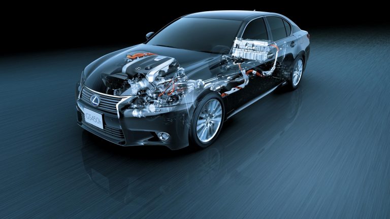
The 2GR-FXE was a 3.5-litre V6 petrol engine that was used in the Lexus AL10 RX 450h and L10 GS 450h. While the 2GR-FXE engine code was used for both engines to denote the ‘Atkinson cycle’ operation of the engine, the engines for these vehicles differed in that the L10 GS 450h had conventional port and direct injection systems, and operated with higher compression ratio.
This article will initially describe the 2GR-FXE engine as it was offered in the AL10 RX 450h, followed by details of the key differences for the L10 GS 450h engine.
[su_table responsive=”yes”]
| Years | CVT | Motors | Peak power | Peak torque | |
|---|---|---|---|---|---|
| Lexus AL10 RX 450h | 2009-15 | 6sp CVT | 3.5-litre petrol V6 | 183kW at 6000rpm | 317Nm at 4800rpm |
| Electric (front | 123kW | 335Nm | |||
| Electric (rear) | 50kW | 139Nm | |||
| Combined | 220kW | N/A | |||
| Lexus L10 GS 450h | 2012-on | 6sp CVT | 3.5-litre petrol V6 | 215kW at 6000rpm | 352Nm at 4500rpm |
| 650V electric motor | 147kW | 275Nm | |||
| Combined | 254kW | N/A |
[/su_table]
Atkinson cycle
Lexus described the 2GR-FXE engine as having an ‘Atkinson cycle’ since the compression stroke was shortened and the expansion stroke extended. This was achieved by keeping the intake valves open during the initial stage of the compression stroke (when the piston was ascending) to allow a reverse flow of intake air into the intake manifold – this allowed for an increase in throttle valve opening in part load conditions, thereby reducing intake manifold vacuum and intake losses. Furthermore, closure of the intake valves was delayed until the end of the expansion stroke, thereby increasing the expansion ratio.
In a conventional (Otto) cycle engine, the compression stroke volume and expansion stroke volume were practically identical, such that the compression ratio and expansion ratio were also identical. Furthermore, any attempt to increase the expansion ratio also increased the compression ratio, and hence the likelihood of engine knock or pre-ignition. Please note that:
- Expansion ratio = (expansion stroke volume + combustion chamber volume)/combustion chamber volume; and,
- Compression ratio = (compression stroke volume + combustion chamber volume)/combustion chamber volume.
For the AL10 RX 450h, the compression ratio of the 2GR-FXE engine was 12.5:1; for the L10 GS 450h, the compression ratio was 13.0:1.
The purpose of the 2GR-FXE engine was to allow the pressure in the combustion chamber at the end of the power stroke to be equal to atmospheric pressure – when this occurred, all available energy was obtained from the combustion process.
Since this ‘Atkinson’ operation used a smaller portion of the compression stroke to compress the intake air, it did not take in as much air as a comparable Otto cycle engine and had lower power density.
2GR-FXE block
With its cast aluminium alloy cylinder block, the cylinder banks of the 2GR-FXE engine had a 60-degree ‘V’ angle. The 2GR-FXE engine had 94.0 mm bores and an 83.0 mm stroke for a capacity of 3456 cc; bore pitch was 105.5 (i.e. the distance between the centre of adjacent bores), while cylinder bank offset was 36.6 mm. Between the cylinder bores, passages existed for coolant flow.
Cylinder head
The 2GR-FXE had an aluminium alloy cylinder head and a steel-laminate type head gasket; to enhance sealing performance and durability, a shim was used around the cylinder bore of the gasket.
The 2GR-FXE engine had upright, ‘Siamese’ inlet ports to reduce the overall surface area of the port walls to reduce wall wetting and hydrocarbon emissions, and a narrow included valve angle to create a compact combustion chamber shape.
To reduce oil loss, the GS 450h was fitted with a cyclone-type oil separator.
Camshafts
The 2GR-FXE engine had double overhead camshafts that were made of cast iron alloy. Both the primary and secondary timing chains used pitch roller chains with a pitch of 9.525 mm. The intake camshafts were driven by the crankshaft via the primary timing chain. The exhaust camshafts were driven by the intake camshaft of the respective bank via the secondary timing chain.
The primary timing chain used one chain tensioner (ratchet type with a non-return mechanism), and each of the secondary timing chains for the right and left banks used one chain tensioner. Both the primary and secondary chain tensioners used a spring and oil pressure to maintain proper chain tension at all times. Furthermore, the timing chains were lubricated by oil jets.
Roller rockers
The 2GR-FXE engine had roller rocker arms with built-in needle bearings that reduced the friction that occurred between the camshafts and the roller rocker arms (which actuated the valves). The hydraulic lash adjuster – located at the fulcrum of the roller rocker arm – consisted primarily of a plunger, plunger spring, check ball and check ball spring. Through the use of oil pressure and spring force, the lash adjuster maintained a constant zero valve clearance.
Engine oil that was supplied via the cylinder head and the built-in spring actuated the hydraulic lash adjuster. The oil pressure and the spring force that acted on the plunger would push the roller rocker arm against the cam to adjust the valve clearance that was created during valve operation. As a result, the lash adjuster maintained constant zero valve clearance.
Valves and Dual VVT-i
The 2GR-FXE engine had four valves per cylinder. Of these, the intake valves had 38.0 mm diameters (with narrow 5.5 mm diameter valve stems) and the exhaust valves had 32.0 mm diameters. The ‘dual variable valve timing with intelligence’ (Toyota’s ‘Dual VVT-i’) system adjusted the intake and exhaust camshafts. Oil passages on the intake and exhaust camshafts enabled the ECU to adjust camshaft advance and retard via:
- An oil control valve (mounted on the cylinder head); and,
- Vane-type actuators on the ends of the four camshafts. The intake side used a VVT-i controller with three vanes, and the exhaust side used one with four vanes.
When the engine stopped, the intake side VVT-i controller was locked on the most retarded angle side by the lock pin, and the exhaust side VVT-i controller was locked on the most advanced angle side.
Intake
For the 2GR-FXE engine, the intake air chamber was made of plastic and contained an intake air control valve for Toyota’s ‘Acoustic Control Induction System’ (ACIS). ACIS consisted of:
- A bulkhead to divide the intake manifold into two stages; and,
- An intake air control valve in the bulkhead which opened and closed to vary the effective length of the intake manifold according to engine speed and throttle valve opening angle.
When the engine was running at middle speed under high load, an actuator would close the intake air control valve to increase the effective length of the intake manifold and improve intake efficiency – at medium engine speeds – due to the effect of inlet pulsations. In any condition other than middle speed running under high loads, the intake air control valve was open to shorten the effective length of the intake manifold.
The intake manifold for the 2GR-FXE engine was made of thin-wall cast aluminium and included a pressure sensor for use with the exhaust gas recirculation system.
Injection: RX 450h
For the RX 450h, the 2GR-FXE engine had an L-type sequential fuel injection system which detected the intake air mass with a hot-wire type air flow meter and a twelve-hole injector for each cylinder. To minimise the distance from the injector to the valve and reduce wall wetting, the injector tip protruded slightly into the inlet port.
D-4S Injection: L10 GS 450h
For the L10 GS 450h, the 2GR-FXE engine had Lexus’ D-4S (‘Direct injection 4-stroke gasoline engine Superior’) injection which consisted of both direct injection and conventional port injection systems, and required separate low- and high-pressure fuel systems. Unlike the related 2GR-FSE engine, however, the port injectors for the GS 450h’s 2GR-FXE engine were only used at idle.
Produced by Denso, the two-slit direct injectors were positioned at the outer side of the intake valves (on the edge of the combustion chamber). These injectors had two inverted V-shaped slits that produced a dual-fan-shaped spray. For the GS 450h, fuel injection pressure for the direct injectors was 18 MPa.
Ignition
The 2GR-FXE engine had a coil-on-plug ignition system, Toyota’s ‘Direct Ignition System’ (DIS), in which the spark plug cap was integrated with the ignition coil. Positioned in the centre of the combustion chamber, the 2GR-FE engine used long-reach iridium-tipped spark plugs so that:
- The top of the combustion chamber could be thicker than normal; and,
- The water jacket could be extended near the combustion chamber for better cooling.
Exhaust and emissions
The 2GR-FXE engine had a stainless steel exhaust manifold and hexagonally-shaped ceramic catalytic converters.
For the RX 450h, the 2GR-FXE engine featured water-cooled exhaust gas recirculation (EGR) in which engine coolant flowed over wave-like fins in the EGR cooler. Furthermore, a specially designed delivery chamber in the intake system distributes the re-circulated gas to each of the six cylinders with a variance of one per cent. An electronic EGR valve – with a stepper-type motor – controlled the flow of recirculated exhaust gases into the delivery chamber. The intake manifold also had a pressure sensor for use with the EGR system.
The longer expansion stroke of the Atkinson Cycle engine resulted in lower exhaust gas temperatures relative to a conventional Otto Cycle engine. The cooled EGR system further reduced exhaust gas temperature from up to 880 degrees (as it was emitted from the combustion chamber) to around 150 degrees Celsius. The effect of the Atkinson cycle and cooled EGR was that additional fuel injection was not required to cool exhaust gases as may otherwise occur during high-load driving. As such, the EGR system provided reduced intake losses, reduced cooling losses and reduced exhaust losses.
For the RX 450h, the 2GR-FXE engine had an Exhaust Heat Recovery (EHR) system that was installed in the exhaust behind the catalytic converter and used an exhaust control valve and thermostat to monitor and manage the flow of gases and coolant through the system. When engine coolant temperatures were low, an internal exhaust control valve would close and force exhaust gases to circulate through the EHR unit and heat the coolant that was passing through the unit. When engine coolant temperatures reach normal operating temperatures, the exhaust control valve would open, allowing exhaust gases to pass through the system normally.
Ancillaries
Since the RX 450h had electric power-assisted steering and electric inverter air conditioning compressor, the 2GR-FXE engine had only one V-ribbed ancillary belt that was used to drive the water pump.
The GS 450h’s 2GR-FXE engine, however, included an electric water pump – such that an ancillary belt was not needed.


