[su_image_carousel source=”media: 52174,52175,52176,52177,52178,52179″]
Introduction
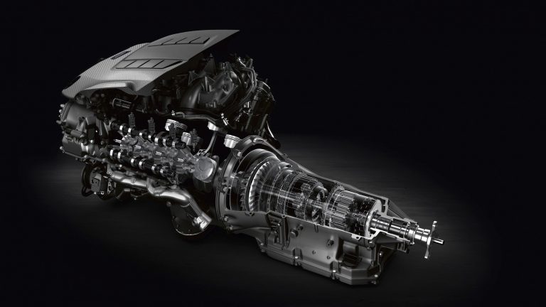
The 2UR-GSE was a 5.0-litre V8 petrol engine with a 90-degree ‘V’ angle that was first introduced in the Lexus IS F. Although based on the related 1UR-FSE engine, the 2UR-GSE underwent extensive changes to suit its more sporting applications. Significantly, the cylinder head for the 2UR-GSE engine was developed by Yamaha and changes included a wider included valve angle, high-flow intake ports, larger valve faces and higher lift valves.
This article will discuss attributes of the 2UR-GSE engine as it was introduced in the Lexus IS F then describe the changes that were introduced for the Lexus RC F.
[su_table responsive=”yes”]
| Engine | Trans. | Years | Peak power | Peak torque | |
|---|---|---|---|---|---|
| Lexus IS F | 5.0-litre petrol V8 | 8sp auto | 2008-13 | 311kW at 6600rpm | 505Nm at 5200rpm |
| Lexus RC F | 5.0-litre petrol V8 | 8sp auto | 2015-on | 351kW at 7100rpm | 530Nm at 4800-5600rpm |
[/su_table]
2UR-GSE block
The 4969 cc 2UR-GSE engine had a die-cast aluminium alloy block with 94.0 mm bores and an 89.5 mm stroke; bore pitch was 105.5 mm, while the cylinder banks had a 21.0 mm offset. On the outside of the block, reinforcing ribs were used for greater rigidity.
Within the bores, the 2UR-GSE engine had spiny-type, thin-wall cast iron liners that were manufactured so that their casting exteriors formed large, irregular surfaces for better adhesion between the liners and the block – this improved heat dissipation and reduced heat deformation of the bores. Furthermore, the 2UR-GSE block had drilled coolant passages between each bore.
Crankshaft, connecting rods and pistons
The 2UR-GSE engine had a forged steel crankshaft with six drilled balance weights and five main bearing journals. The crankshaft bearings were made of aluminium alloy, while the bearing lining surface was coated with resin to improve wear and seizure resistance. The crankshaft bearing caps had four plastic region tightening bolts of different sizes in the inner and outer sides to secure the journals; each crankshaft bearing cap was tightened laterally to improve reliability. To reduce noise and vibration, the crankshaft pulley had a double torsional damper.
The 2UR-GSE engine had 144.25 mm long connecting rods that were forged from iron-sintered alloy and operated on resin-coated aluminium bearings. To minimise the shifting of the bearing caps during assembly, knock pins were used at the mating surfaces of the bearing caps. The connecting rods did not have nuts on their big-ends, but used plastic-region tightening bolts to maximise clamping force and minimise weight
The 2UR-GSE engine had 94.0 mm diameter aluminium alloy pistons that were cooled by four oil jets in the cylinder block. The piston crown had a shallow combustion chamber and valve clearance cut outs.
Cylinder head
Like the 1UR-FSE, the 2UR-GSE engine had an aluminium alloy cylinder head that separated the cam journal portion (camshaft housing) from the cylinder head. The cylinder head was mounted on a three-layer steel-laminate type cylinder head gasket, while a shim was used around the cylinder bore of each gasket to enhance sealing and durability.
The 2UR-GSE had magnesium alloy cylinder head covers which included an oil delivery pipe for lubrication of the sliding parts of the valve rocker arms. To improve cooling around the spark plug, the 2UR-GSE cylinder head also had water jackets between the exhaust port and the spark plug. Furthermore, fresh air was drawn from the right and left bank cylinder head covers to improve ventilation inside the engine and improve the deterioration resistance of the engine oil.
Camshafts and timing chains
The 2UR-GSE engine had hollow double overhead camshafts per cylinder bank. During production, the camshafts were cooled by liquid nitrogen before separate forged cam lobes were attached – this this process facilitated the machining and polishing of a more exact cam profile to enhance engine power output.
The 2UR-GSE used separate, primary timing chains for the intake camshafts, while each exhaust camshaft was driven by a secondary timing chain from the intake camshaft. Both the primary and secondary timing chains were roller-type chains with a pitch of 9.525 mm. Each primary timing chain and secondary timing chain had a chain tensioner that used oil pressure and a spring to maintain chain tension. A chain oil jet in the oil pump cover was used to lubricate the timing chains.
Valves
The 2UR-GSE engine had four valves per cylinder – two intake and two exhaust – that were actuated by roller rocker arms with needle-roller bearings. Unlike the 1UR-FSE, the 2UR-GSE engine had fixed pivot rocker arms such that it did not require hydraulic lifters. To minimise friction, the sliding part of the rocker arm and camshaft lobes were lubricated.
Located at the fulcrum of the roller rocker arm, the 2UR-GSE engine had a hydraulic lash adjuster which consisted of a plunger, a plunger spring, a check ball and a check ball spring. The hydraulic lash adjuster was actuated by engine oil supplied from the cylinder head and an integrated spring. The oil pressure and the spring force that acted on the plunger pushed the roller rocker against the cam to adjust the clearance between the valve stem and rocker arm.
The 2UR-GSE engine featured titanium inlet valves, while the ‘umbrellas’ of the exhaust valves were made from nickel-rich heat-resistant steel alloy. For the 2UR-GSE engine in the Lexus IS F, valve dimensions and lift were as follows:
- Intake valve diameter: 38.0 mm;
- Intake valve lift: 12.0 mm;
- Exhaust valve diameter: 32.0 mm; and,
- Exhaust valve lift: 11.0 mm.
Dual VVT-i with VVT-iE
The 2UR-GSE engine had the Toyota/Lexus ‘Dual VVT-i’ system to control the inlet and exhaust camshafts and vary valve timing to optimise valve overlap according to engine and driving conditions to make full use of exhaust pulsation to enhance cylinder filling at high engine speeds.
For the inlet camshafts, the 2UR-GSE engine had ‘Variable Valve Timing – intelligent Electric’ (VVT-iE) which used an electric motor to vary the VVT-i controller vane for camshaft advance or retard. In contrast, the exhaust camshaft had a conventional hydraulic VVT-i system in which the camshaft timing oil control valve controlled a spool valve that enabled hydraulic pressure to be applied to the advance or retard side of the VVT-i controller. In response, rotation of the VVT-i controller vane sub-assembly – relative to the timing chain sprocket – varied valve timing.
The VVT-iE system was developed because hydraulic VVT-i could not operate below engine speeds of 1000 rpm or when the engine was cold. VVT-iE, however, could operate at all engine speeds and temperatures, with a cam response speed of 50 degrees per second in the retardation phase and 150 degrees per second in the advance phase.
For VVT-iE, the 2UR-GSE engine featured a high-precision-finish plate and narrow pins at the interface of the speed reduction gear and phase converter to transmit the VVT-iE electric motor’s high rotation torque. Due to the hardness of these elements, a scroll machine – based on the mechanics of a tool used for cutting air conditioner parts – was used to achieve the required base-cutting precision.
For the camshaft motor control components, VVT-iE required:
- Uniform winding of the high density coils for matched magnetisation within each stator core;
- Precision milling of the motor shaft bearings so that VVT-iE could operate with minimal vibration; and,
- A new system that employed frictional resistance and speed-reduction gearing to hold the cam phase in the ideal position for engine start-up.
For the 2UR-GSE engine in the Lexus IS F, dual VVT-i provided:
- A valve overlap range (the period when both the exhaust and inlet valves were open) from minus 10 degrees to a maximum of 65 degrees;
- A 40 degree range of inlet camshaft timing variation relative to crankshaft angle;
- A 35 degrees of exhaust camshaft timing variation relative to crankshaft angle;
- Inlet camshaft duration of 248 degrees; and,
- Exhaust camshaft duration of 244 degrees.
Intake and throttle
The 2UR-GSE engine had a dual intake system which consisted of primary and secondary air ports. At low to medium engine speeds, the system used the primary intake port only to optimise low-end torque. At higher engine speeds, however, both intake ports would open to optimise air flow to the engine and reduce the effective length of the intake tract for top-end power.
For the 2UR-GSE engine, intake pressure losses were reduced and the volume of intake air increased by tuning the shape of the high pressure areas in the port. For example, the cross-sectional area of the port was increased by using smaller port injectors which improved intake pulsation efficiency and increased intake air volume.
The 2UR-GSE had an electronically controlled throttle which used the ECM to calculate the optimal throttle valve angle and a throttle control motor to control the angle. The 2UR-GSE engine featured a specially machined electronic throttle shaft – which was machined down from a 10.0 mm diameter to 7.0 mm – which increased intake air passage area and reduced intake air resistance.
D-4S Injection
Like the 1UR-FSE, the 2UR-GSE engine had ‘Direct-injection 4-stroke Superior’ (D-4S) which featured two injectors per cylinder: one injector in the combustion chamber and a second in the intake port. The 2UR-GSE engine could therefore use:
- Direct injection only; or
- Both direct injection and port injection.
The 2UR-GSE engine could also vary the injection timing phase of the two systems.
The 2UR-GSE engine had two fuel supply systems, low-pressure and high-pressure, for the port injectors and direct injectors, respectively. While the twelve-hole port injectors injected fuel at a maximum pressure of four bar, the direct injectors had twin 0.52 mm by 0.13 mm rectangular slits which produce a double-fan, 130-bar injection pattern.
With direct injection, the injection of petrol into the combustion chamber (during the downstroke of the piston) and its subsequent evaporation produced a cooling effect that increased intake air volume and improved charging efficiency. Furthermore, the intake air formed a vertical swirl current (tumble current) to promote improve air/fuel mixing and hence improve performance and emissions.
To resist deposits, the direct injectors had a special coating on their nozzles. Furthermore, the area where the injector body met the cylinder head had an insulator and the injector shaft had two Teflon seals to resist cylinder pressure, improve sealing performance and reduce vibration.
For the IS F, D4-S had the following operating scenarios:
- Under cold start conditions, D-4S used port injection during the intake stroke and direct injection during the compression stroke. This produced an air:fuel mixture of 15-16:1, generating a richer mixture around the spark plug and raising the temperature of exhaust gases for faster warm-up of the two thin-wall catalysts;
- At idle, the engine operated on direct injection alone due to its higher efficiency;
- At low to medium loads and lower engine speeds, both direct and port injection systems were used during the intake stroke. This created a homogeneous 12-15:1 air:fuel ratio to stabilise combustion, improve fuel efficiency and reduce NOx and HC emissions; and,
- Under heavy loads, direct injection alone was used with an 11.8:1 air:fuel ratio during the intake stroke. The use of direct injection at high engine loads created an intake cooling effect which improved the efficiency of each charge. The 2UR-GSE engine could therefore use a high compression ratio while reducing pre-ignition tendencies and improving engine output and performance.
While the 2UR-GSE engine for the Lexus IS F had a compression ratio of 11.8:1, this was increased to 12.3:1 for the Lexus RC F.
The firing order of the 2UR-GSE engine was 1-8-7-3-6-5-4-2.
Ignition
The 2UR-GSE engine had Toyota’s independent ‘Direct Ignition System’ (DIS) ignition system which used one ignition coil (with integrated igniter) for each cylinder. Ignition timing was determined by the ECM based on signals from sensors and adjusted in response to engine knocking. The 2UR-GSE had four knock sensors that were positioned in the V-bank of the engine.
The 2UR-GSE engine had long-reach, iridium-tipped spark plugs – poisoned in the centre of the combustion chamber – so that the surrounding cylinder head could be made thicker and the water jacket near the combustion chamber extended.
Exhaust
The 2UR-GSE engine had stainless steel, ‘semi-dual’ exhaust manifolds which divided the traditional single manifold into two by connecting non-adjoining cylinders based on the engine ignition sequence. According to Lexus, the connection of cylinders with long ignition intervals minimised exhaust counter-pressure interference to ensure the smoothest possible flow of exhaust gases.
The 2UR-GSE engine had stainless steel exhaust pipes; the front exhaust pipe had two ceramic three-way catalytic converters on both the left and right exhaust pipe banks. For the Lexus IS F,
- The front exhaust pipes had a diameter of 60.5 mm;
- The single central pipe had a 70.0 mm diameter;
- The dual muffler inlet pipes had a 54.0 mm diameter to reduce back pressure;
- To reduce back pressure, the IS F had dual 16.8-litre main mufflers and four tailpipes.
For emissions control, the 2UR-GSE engine had integrated catalytic converters.
2UR-GSE: Lexus RC F
For the Lexus RC F, the 2UR-GSE benefited from extensive changes relative to the engine in the Lexus IS F.
Atkinson cycle
Significantly, the 2UR-GSE engine for theRC F could switch to an ‘Atkinson cycle’ at cruising speeds for better fuel economy. In a conventional (Otto) cycle engine, compression stroke volume and expansion stroke volume are practically identical, such that the compression ratio and expansion ratio are also identical. Hence, any attempt to increase the expansion ratio also increases the compression ratio, and hence the likelihood of engine knock or pre-ignition. Please note that:
- Expansion ratio = (expansion stroke volume + combustion chamber volume)/combustion chamber volume; and,
- Compression ratio = (compression stroke volume + combustion chamber volume)/combustion chamber volume.
Lexus described the 2UR-GSE engine as having an ‘Atkinson cycle’ since the compression stroke was shortened and the expansion stroke extended. This was achieved by keeping the intake valves open during the initial stage of the compression stroke (when the piston was ascending) to allow a reverse flow of intake air into the intake manifold – this allowed for an increase in throttle valve opening in part load conditions, thereby reducing intake manifold vacuum and pumping losses. Furthermore, closure of the intake valves was delayed until the end of the expansion stroke, thereby increasing the expansion ratio.
Since this ‘Atkinson’ operation used a smaller portion of the compression stroke to compress the intake air, it did not take in as much air as a comparable Otto cycle engine and had lower power density, yet higher thermal efficiency.
Internal components
While maximum engine speed for the Lexus IS F was 6800 rpm, this was increased by 500 rpm to 7300 rpm for theRC F due to lighter internal components. These included –
- A new crankshaft: crank pin diameter, crank counter-weight size and big-end bearing size were all reduced for lower reciprocating weight;
- New connecting rods with new main-bearing materials;
- New piston and piston rings; and,
- New intake and exhaust valvetrains.
Cylinder head and camshafts
For theRC F the 2UR-GSE had a new cylinder head which featured improved porting and a high-flow/high tumble ratio. Furthermore, a new throttle body was increased with an 83 mm diameter (previously 76 mm) for greater power. The water jackets in the cylinder head were also redesigned to enhance cooling performance and accommodate the higher heat build-up from the increased power output.
TheRC F benefited from new camshafts profiles that provided greater valve lift and increased range of adjustment for the VVT-iE system.
Injection and ignition
For the RC F, the maximum pressure for the direct injectors increased to 180 bar (previously 130 bar) and the spray shape was improved. Furthermore, the compression ratio was raised to 12.3:1 and new spark plugs were introduced.
Intake and exhaust
The RC F engine was fitted with a new intake manifold which optimised runner length and diameter; the intake manifold ports were also painted blue. To reduce back-pressure, new four-into-two exhaust headers were introduced.


