[su_image_carousel source=”media: 52222,52223,52224,52225,52226,52227,52228,52229″]
Introduction
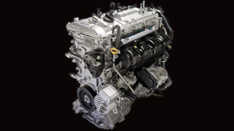
Toyota’s 2ZR-FXE was a 1.8-litre four-cylinder petrol engine that was a member of Toyota’s ‘ZR’ engine family. Like the 2ZR-FE on which it was based, the 2ZR-FXE engine had an aluminium alloy cylinder block and head, offset crankshaft, double overhead camshafts and four valves per cylinder. The 2ZR-FXE engine, however, was distinguished by its:
- Atkinson cycle operation;
- VVT-i (‘Variable Valve Timing – intelligent’) for the intake camshaft only;
- Cooled exhaust gas recirculation (EGR) system; and,
- Compression ratio of 13.0:1.
For the Toyota XW30 Prius, the 2ZR-FXE replaced the 1.5-litre 1NZ-FXE petrol engine. As per the table below, the 2ZR-FXE engine was offered in the Toyota XW30 Prius, Lexus CT 200h and Toyota ZVW40 Prius v.
[su_table responsive=”yes”]
| Engine | Trans. | Peak power | Peak torque | |
|---|---|---|---|---|
| Toyota XW30 Prius, Lexus CT 200h, Toyota ZVW40 Prius v |
1.8-litre Atkinson cycle petrol I4 | CVT | 73kW at 5200rpm | 142Nm at 4000rpm |
[/su_table]
2ZR-FXE block
The 1798 cc 2ZR-FXE engine had a die-cast aluminium alloy block with 80.5 mm bores and an 88.3 mm stroke; for compact dimensions, the 2ZR-FXE engine had 7 mm between its cylinder bores for compact dimensions.
The 2ZR-FXE engine had spiny-type cast iron liners in which the casting exteriors formed large irregular surfaces to enhance adhesion between the liners and the aluminium cylinder block – this aided heat dissipation, reduced heat deformation of the cylinder bores and lowered operating temperature.
Within the blowby gas passage of the cylinder block, the 2ZR-FXE engine had an oil separator which separated engine oil from the blowby gas to reduce oil degradation and the consumption of engine oil.
Crankshaft, connecting rods and pistons
The 2ZR-FXE crankshaft had five journals and eight balance weights. To reduce the forces on the side of the cylinder walls, the crankshaft was offset by 8 mm to the intake side of the bore centres. Furthermore, the lining surface of the big-end crankshaft bearings was micro-grooved to optimise oil clearance, improve cold-cranking performance and reduce vibration.
The 2ZR-FXE engine had steel connecting rods and, to reduce mass, plastic region tightening bols. Like the crankshaft bearings, the lining surface of the connecting rod bearing was micro-grooved.
The 2ZR-FXE engine had aluminium alloy piston with full floating-type piston pins. To reduce friction, the 2ZR-FXE engine had low tension piston rings and resin-coated piston skirts. The groove of the top piston ring underwent a hard anodizing treatment for abrasion resistance, while the no.1 compression ring had an inside bevel shape to reduce blowby gas and a Physical Vapor Deposition (PVD) coating for wear resistance. The 2ZR-FXE cylinder block contained piston oil jets for cooling and lubrication – these jets contained a check ball to prevent oil from being fed when oil pressure was low.
2ZR-FXE: Atkinson cycle
In a conventional (Otto) cycle engine, compression stroke volume and expansion stroke volume are practically identical, such that the compression ratio and expansion ratio are also identical. Hence, any attempt to increase the expansion ratio also increases the compression ratio, and hence the likelihood of engine knock or pre-ignition. Please note that:
- Expansion ratio = (expansion stroke volume + combustion chamber volume)/combustion chamber volume; and,
- Compression ratio = (compression stroke volume + combustion chamber volume)/combustion chamber volume.
Toyota described the 2ZR-FXE engine as having an ‘Atkinson cycle’ since the compression stroke was shortened and the expansion stroke extended. This was achieved by keeping the intake valves open during the initial stage of the compression stroke (when the piston was ascending) to allow a reverse flow of intake air into the intake manifold – this allowed for an increase in throttle valve opening in part load conditions, thereby reducing intake manifold vacuum and pumping losses. Furthermore, closure of the intake valves was delayed until the end of the expansion stroke, thereby increasing the expansion ratio.
Since this ‘Atkinson’ operation used a smaller portion of the compression stroke to compress the intake air, it did not take in as much air as a comparable Otto cycle engine and had lower power density, yet higher thermal efficiency.
Toyota quoted the 2ZR-FXE engine as having a compression ratio of 13.0:1.
Intake and throttle
The 2ZR-FXE engine had a plastic inlet to reduce mass and heat transfer from the cylinder head. The 2AR-FE engine had a linkless-type throttle body and Toyota’s ‘Electronic Throttle Control System – intelligent’ (ETCS-i) which controlled throttle valve opening according to with the amount of accelerator pedal effort and the condition of the engine. To improve the flow of air within the intake manifold, mesh was used between the throttle body and the intake manifold.
The 2ZR-FXE engine had upright, Siamese-type intake ports to increase intake efficiency and reduce the overall surface area of the intake port walls.
Cylinder head
The 2ZR-FXE engine had an aluminium cylinder head that was mounted on a triple-layer metal type cylinder head gasket. The die-cast aluminium cylinder head cover contained an oil delivery pipe for lubrication of the sliding parts of the roller rocker arm.
Camshafts
The 2ZR-FXE engine had double overhead camshafts – made from cast iron alloy – that were driven by a roller chain that had an 8 mm pitch. To lubricate the chain, the die-cast aluminium timing chain cover contained an oil jet. The ratchet-type chain tensioner had a non-return mechanism and used a spring and oil pressure to maintain chain tensioner; the tensioner also suppressed noise generated by the timing chain.
For the 2ZR-FXE engine, the cam profile was designed with an indented R (radius) to increase valve lift when the valves began to open and finished closing.
Valves
The 2ZR-FXE engine had four valves per cylinder – two intake and two exhaust – that were actuated by roller rocker arms which had built-in needle bearings to reduce friction between the cams and roller rocker arms.
At the fulcrum of each roller rocker arm there was a hydraulic lash adjuster which consisted of a plunger, plunger spring, check ball and check ball spring. The oil pressure and the spring force that acted on the plunger pushed the roller rocker arm against the cam to adjust the valve clearance that was created during the opening and closing of the valve. As a result, the hydraulic lash adjusters maintained constant zero valve clearance.
The 2ZR-FXE engine had an included valve angle of 29 degrees. Valve specifications for the 2ZR-FXE were as follows:
- Intake valve diameter: 31.9 mm;
- Intake valve length: 109.3 mm;
- Exhaust valve diameter: 27.4 mm;
- Exhaust valve length: 108.3 mm;
- Valve stem diameter: 5.5 mm.
Variable Valve Timing – intelligent (VVT-i)
For the 2ZR-FXE engine, Toyota’s ‘variable valve timing with intelligence’ (VVT-i) provided continual variations of the intake valve timing according to engine speed, throttle position, inlet camshaft angle, engine coolant temperature and intake air volume.
VVT-i was controlled by the ECU and implemented via an oil-pressure activated ‘push-push’ type system. Specifically, the hardware for the VVT-i system consisted of:
- A camshaft timing oil control valve – mounted adjacent to the inlet camshaft gear wheel – that was controlled via a coil and plunger by the ECU. When the ECU sought to vary valve timing, it directed a signal to the spool-type oil control valve to provide oil pressure to either the ‘advance’ or ‘retard’ side of the four vane chambers; and,
- A VVT-i controller mechanism that consisted of a housing on the front of the timing wheel – driven via the timing chain – and a four-bladed vane that was coupled with the intake camshaft.
Inlet cam timing was set to the maximum retard position for engine start-up, operation at low engine temperature, idle and engine shut-down. To prevent any knocking noise, a locking pin in the controller locked the camshaft timing in the maximum retard position for engine start-up and immediately thereafter until oil pressure was established.
Injection and ignition
The 2ZR-FXE engine had sequential fuel injection via long-nozzle, 12-hole injectors. The 2ZR-FXE engine had pentroof type combustion chambers and both the cylinder head and the piston crown had taper squish areas around the circumference of the chambers to improve intake efficiency and anti-knocking performance.
The 2ZR-FXE engine had Toyota’s ‘Direct Ignition System’ (DIS) in which there was one ignition coil (with igniter) for each cylinder. With Toyota’s ‘Electronic Spark Advance’ (ESA), ignition timing was determined by the ECM based on inputs from sensors and adjusted according to knocking.
The 2ZR-FXE engine had long-reach, thin-electrode type iridium tipped spark plugs that were located at the centre of the combustion chamber. Firing order for the 2ZR-FXE engine was 1-3-4-2.
Exhaust, EGR and EHR
The 2ZR-FXE engine had a stainless steel exhaust manifold with two integrated three-way catalytic converters. Ball joints were used to join the exhaust manifold to the front exhaust pipe and the front pipe to the tailpipe.
The 2ZR-FXE engine had a cooled Exhaust Gas Recirculation (EGR) system. By recirculating cooled, inert exhaust gases into the intake system, the EGR system reduced exhaust gas temperatures, intake losses, cooling losses and exhaust losses.
The 2ZR-FXE engine had an ‘Exhaust Heat Recovery’ system that used exhaust gases to warm engine coolant as it passed through the EHR unit. As such, the EGR system reduced the time needed for the engine to reach operating temperature, thereby reducing fuel consumption and CO2 emissions during the warm-up phase. The exhaust heat recovery system was installed in the exhaust behind the catalytic converter and employed an exhaust control valve and thermostat to monitor and manage the flow of gases and coolant through the system. Once coolant temperatures had reached operating temperatures, the exhaust control valve would open to allow exhaust gases to pass through the exhaust system normally.


