[su_image_carousel source=”media: 51158,51159,51160,51161,51162,51163,51164,51165,51166,51167,51168,51169″]
Introduction
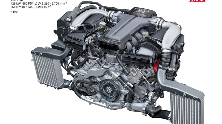
Audi’s BUH was a 5.0-litre biturbo V10 petrol engine that powered the Audi C6 RS6. Effectively replacing the 4.2-litre biturbo BCY engine, key features of the BUH engine included its:
- Aluminium-silicon alloy (AlSi17Cu4Mg) block with a 90 degree ‘V’ angle;
- Aluminium alloy cylinder head;
- Chain-driven double overhead camshafts with an adjustment range of 42 degrees for variable intake and exhaust timing;
- Four valves per cylinder actuated by roller finger cam followers;
- IHI RHF55 turbochargers (one per cylinder bank) which provided boost pressure of 1.6 bar;
- Dry sump lubrication;
- Homogenous direct injection (Audi’s ‘Fuel Stratified Injection’ or FSI) at a pressure of up to 120 bar;
- Compression ratio of 10.5:1;
- Two Bosch ME 9.1.2 engine control units; and,
- Euro 4 emissions compliance.
The BUH engine had a 560 mm long cylinder block, 670 mm overall length, 790 mm width and 655 mm height. Furthermore, the BUH engine weighed 278 kilograms.
For the Audi C6 RS6, the BUH engine was mated to a six-speed ZF 6HP26A automatic transmission.
[su_table responsive=”yes”]
| Model | Engine | Trans. | Peak power | Peak torque |
|---|---|---|---|---|
| Audi C6 RS6 | 5.0-litre BUH biturbo petrol V8 | 6sp auto | 426kW at 6250-6700rpm | 650Nm at 1500-6250rpm |
[/su_table]
Block
Like Audi’s naturally aspirated 5.2-litre BXA engine, the BUH engine had a hypereutectic aluminium-silicon alloy (AlSi17Cu4Mg) block that was produced through low-pressure gravity die-casting. Bolted to the bottom of crankcase, the bedplate was cast from AlSi12Cu1 and reinforced with cast-in GGG50 inserts – attached with four screws – to reduce thermal expansion and play in the main crankshaft bearings at high temperatures.
The BUH engine had 84.5 mm bores that were spaced at 90 mm intervals and an 89.0 mm stroke for a capacity of 4991 cc. Furthermore, the cylinder banks had an 18.5 mm offset. Rather than having separate liners, the cylinder bores of the BUH engine were mechanically stripped to separate the aluminium in a three-stage honing and exposure process. By stripping the aluminium from the cylinder surfaces, silicon was exposed in the form of very small and hard particles; these silicon particles were then honed under simulated mechanical stress.
The BUH engine did not have balance shafts.
Crankshaft, connecting rods and pistons
The BUH engine had a forged steel crankshaft with a crank pin that spanned its entire length (unlike the split pin design of the BXA engine). Furthermore, the BUH engine had forged connecting rods and cast aluminium alloy pistons, the latter with newly developed ring packs.
Cylinder head
The BUH engine had an aluminium alloy cylinder head with double overhead camshafts per cylinder bank. The chain drive system for the BUH engine used four 3/8″ simplex roller chains that were mounted on the flywheel side of the engine. Specifically,
- Roller chain A distributed power from the crankshaft to two intermediate sprockets;
- Roller chains B and C distributed power from these sprockets through additional sprockets to the camshafts; and,
- Roller chain D was driven by the crankshaft and drove the engine oil pump, water pump, A/C compressor, power steering pump and the balance shaft.
All chains were tensioned by hydraulic tensioners.
The BUH engine had variable intake and exhaust camshaft timing over a range of 42 degrees relative to the crankshaft. The adjusters were hydraulically controlled, but were mechanically locked into place until sufficient oil pressure was developed. The adjustment range of the camshafts is 42 degrees.
The BUH engine had four valves per cylinder that were actuated by roller finger cam followers which had hydraulic clearance adjustment. The intake and exhaust valves had 33.9 and 28.0 mm diameter heads, respectively. For heat dissipation, the stems of the exhaust valves were filled with sodium.
IHI RHF55 turbochargers
The BUH engine had an IHI RHF55 ball-bearing type turbocharger for each cylinder bank (part numbers 07L 145 701J and 07L 145 702J). Together, the turbochargers provided peak charge (or boost) pressure of 1.6 bar (23.2 psi). At full load, the turbochargers could theoretically compress up to 2200 cubic metres of air per hour.
In response to inputs from the boost pressure sensor in the intake manifold, solenoid control valves could actuate the wastegate. When opened, the wastegate valve provided a bypass channel for a portion of the exhaust gases – this enabled the rotational speed of the turbine to be controlled and, therefore, charge pressure.
To avoid pumping the turbochargers when a sudden transition was made from high load to over-run, two divert air valves were used. The engine management system could activate the divert air valves via an electrical changeover valve.
Charge pressure cooler (intercooler)
The charge air coolers received cooling air from air intakes in the bumper and air vents in the wheel housing liners. The charge air coolers increased the density of the intake air for greater efficiency and the lower temperature also suppressed knocking. The compressed air streams then converged and were distributed to the individual cylinders in the intake manifold.
Intake
The BUH engine had a dual intake air system with two air filter housings mounted on each bank of cylinders. The intake manifold was made from pressure-cast aluminium and contained flaps that were map-controlled by the Engine Control Module. At engine speeds below 3500 rpm, the intake manifold flaps were brought into contact with the port baffles to seal the lower part of the intake port. As a result, the intake air flowed through the upper section of the intake port and induced a tumbling motion inside the cylinder. When not activated, the intake manifold flaps were in the ‘open’ position which maximised the cross-sectional area of the intake port to reduce intake resistance at higher engine speeds.
Oil supply and lubrication
The BUH engine had a dry-sump lubrication system to maintain lubrication of engine components for lateral accelerations exceeding 1.2 g. Since the BUH engine did not have an oil pan, an oil pump extracted oil from the bearings, cylinder head and chain drive via an oil pump to the oil reservoir. Oil passing through the oil pump in the oil reservoir went through a double-flow pipe which discharged into a cyclone that, in turn, rotated and de-gassed the oil. From there, oil was pumped under pressure into the oil circulation circuit; depending on oil temperature, oil was either pumped directly or via an auxiliary air/oil cooler.
Fuel Stratified Injection (FSI)
The fuel system for the BUH engine consisted of a low-pressure circuit which used an electric transfer fuel pump and a high-pressure circuit which used two high pressure fuel pumps (one for each cylinder bank).
In normal operation, fuel was injected from the common rail directly into the combustion chambers at a pressure of up to 120 bar to form a homogenous air/fuel mixture. Upon injection, the petrol would evaporate and provide a cooling effect within the cylinder – this enabled the BUH engine to operate at a compression ratio of 10.5:1.
Ignition
The BUH engine had mapped direct ignition with centrally-mounted spark plugs and ten single-core ignition coils. The injection and ignition process was controlled by two Bosch Motronic MED 9.1.2 control modules in a master and slave arrangement. The firing order of the BUH engine was 1-6-5-10-2-7-3-8-4-9.
Exhaust
As a 90 degree V10 engine, each cylinder bank of the BUH engine had an interval of 144 degrees between adjacent cylinder ignition points which resulted in exhaust opening periods of 210 degrees and partial overlap between the exhaust phases. To prevent reverse pulsation of expelled exhaust gases in the still-open exhaust port, the exhaust manifold had a 2-1-2 manifold runner design. As such, the exhaust ports for each bank of five cylinders was joined to three exhaust manifold runners, with the mating of the exhaust runners for the cylinders was determined by their sequence in the firing order. Specifically,
- On the left bank, the runners for cylinders 6 and 7 were joined into one exhaust runner, while cylinders 9 and ten were joined into another; the exhaust port for cylinder 8 was a separate runner. The manifold runners for cylinders 6, 7 and 8 were then joined to one catalytic converter while the exhaust runners for cylinders 9 and 10 were joined to another; and,
- On the right bank, the runners for cylinders 1 and 2 were joined into one exhaust runner, while cylinders 4 and 5 were joined into another. The exhaust port for cylinder 3 was a separate runner. The manifold runners for cylinders 1, 2 and 3 were joined to one catalytic converter, while the exhaust runners for cylinders 4 and 5 were joined to another.


