[su_image_carousel source=”media: 51188,51189,51190,51191,51192,51193,51194,51195″]
Introduction
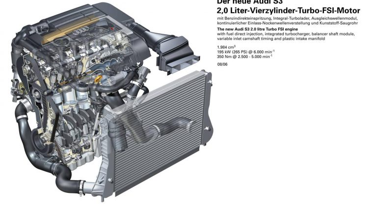
Audi’s BZC and CDLC were 2.0-litre turbocharged petrol engines that were members of Volkswagen’s EA113 engine family and powered the Australian-delivered Audi 8P S3. In Europe, the 8P S3 was powered by the BHZ and CDLA engines, though these engines are understood to have the same basic properties.
Compared to the 2.0 TFSI engine in the Volkswagen Mk.5 Golf GTi (engine codes: AXX, BWA, BPY and CAWB), changes for the Audi 8P S3’s BZC and CDLC engines included:
- A reinforced cylinder block at the main-bearing pedestals and main-bearing caps;
- A new high-flow cylinder head made from aluminium-silicon alloy for high temperature resistance;
- Long-duration camshafts and revised exhaust camshaft timing;
- Uprated piston (wrist) pins, piston rings and connecting rods with new bearings;
- Annular valve seats;
- A larger BorgWarner K04 turbocharger which provided peak boost pressure of 1.2 bar (up from 0.9 bar);
- A larger intercooler and radiator cores;
- A lower compression ratio of 9.8:1 (compared to 10.5:1);
- A redesigned fuel pump and high-pressure injectors with increased cross-section;
- Four oxygen sensors;
- A relocated diverter valve; and,
- An upgraded positive crankcase ventilation (PCV) system.
The BZC/CDLC engine was 625 mm long, 648 mm wide and 666 mm high; it weighed 152 kg.
[su_table responsive=”yes”]
| Model | Engine | Trans. | Peak power | Peak torque |
|---|---|---|---|---|
| Audi 8P S3 (Australia) | 2.0-litre BZC/CDLC turbo petrol I4 | 6sp man. | 188kW at 6000rpm | 330Nm at 2500-5000rpm |
| Audi 8P S3 (Europe) |
2.0-litre BHZ/CDLA turbo petrol I4 | 6sp man. | 195kW at 6000rpm | 350Nm at 2500-5000rpm |
[/su_table]
Block
The BZC/CDLC engine had a grey cast iron (CG25) block with 82.5 mm bores and a 92.8 mm stroke for a capacity of 1984 cc. Within the cylinders, the contact surfaces were honed by liquid blasting. Furthermore, the BZC/CDLC engine had a die-forged steel crankshaft which operated on five main bearings.
To offset second degree inertial forces, the BZC/CDLC engine had two chain driven counter-rotating balance shafts that rotated at twice the speed of the crankshaft.
Crankcase breather system
The BZC/CDLC engine had a crankcase breather system whereby blow-by gases from the crankcase were passed via the primary oil separator in the oil filter module to the cylinder head cover. When this occurred, the blow-by gases were mixed with those from the cylinder head and passed through a labyrinth where further oil separation occurred.
Cylinder head
The BZC/CDLC engine had a cast aluminium alloy cylinder head with double overhead camshafts. While the intake camshaft was driven by a roller chain, the exhaust camshaft was belt-driven and had an elliptical toothed belt pulley on the crankshaft to reduce rotational vibrations on the camshaft and pulling forces on the toothed belt. The intake camshaft was continuously adjustable over a range of 42 degrees relative to the crankshaft.
The BZC/CDLC engine had four valves per cylinder that were actuated by roller finger cam followers with hydraulic valve clearance compensation. For heat dissipation, the exhaust valve stems were filled with sodium.
BorgWarner K04 turbocharger
The BZC/CDLC engine had a single water-cooled BorgWarner K04 turbocharger which provided peak boost pressure of 1.2 bar (17.4 psi); specifications are given in the table below. For the BZC and CDLC engines, the cast steel casing of the turbocharger was produced as a single piece (including the manifold) and could withstand exhaust gas temperatures of up to 1050 degrees.
[su_table responsive=”yes”]
| BZC/CDLC: K04 turbocharger | ||
|---|---|---|
| Turbine | Blade diameter (inducer/exducer) | 44.5 mm / 51.0 mm |
| Number of blades | 12 | |
| Compressor | Blade diameter (inducer/exducer) | 46.4 mm / 60.5 mm |
| Number of blades | 6 + 6 | |
[/su_table]The speed of the turbine, and hence charge pressure, was controlled by a charge pressure control solenoid valve and vacuum unit, with the latter actuating the wastegate valve via a linkage. When opened, the wastegate valve created a channel for exhaust gases to bypass the turbine.
To prevent the turbocharger from braking too heavily in overrun and between gear changes, an electric air recirculation valve was used. Ordinarily, pressure would accumulate in the compressor housing during overrun due to the prevailing charge pressure – this pressure build-up would cause the compressor wheel to brake heavily, leading to a reduction in the prevailing charge pressure (turbo drop). To prevent this from happening, the air recirculation valve was opened by an electric servo motor, creating a bypass channel for compressed air to flow from the compressor wheel back to the suction side of the compressor circuit, thereby keeping the turbine at a constant speed. When the throttle valve was opened, the turbocharger air recirculation valve would close and charge pressure was restored.
Intercooler
After the turbocharger, the intake air passed through a charge air cooler (or intercooler) which reduced the temperature of the air to increase its density. Both the intercooler housing and the mesh through which the air passed were made from aluminium. Furthermore, the intercooler was capable of an air throughput of 850 kilograms per hour (i.e. 650,000 litres of air per hour).
Variable intake manifold
The BZC/CDLC engine had a two-stage variable intake manifold (VIM) which was controlled by the engine management system and used a solenoid valve to vary the length of the intake manifold runners. At low engine speeds, the long intake runner was used to increase pulsation effects and torque output. At higher engine speeds, however, the short intake runner was used to reduce intake resistance and increase power output.
Fuel Stratified Injection (FSI)
The BZC/CDLC engine had Audi’s ‘Fuel Stratified Injection’ or ‘FSI’ which directed fuel directly into the combustion chamber (as opposed to port injection which injected fuel upstream of the chamber) at a pressure of up to 110 bar. The high-pressure fuel pump was driven by a four-fold cam on the exhaust camshaft.
Fuel was only injected in the piston’s compression phase (rather than the conventional induction phase) and was directed into the intake air stream as it moved towards the spark plug. The BZC/CDLC engine had two injection modes:
- Dual injection for cold starts: a special mode for rapid heating of the catalytic converter, the primary injection occurred on the intake stroke at approximately 300 degrees before top dead centre (TDC) of ignition and the fuel distributed itself homogeneously. The second injection occurred at approximately 60 degrees before TDC in the compression phase. The richer mixture formed around the spark plug such that timing could be retarded and, since the exhaust valves were open during combustion, the hotter exhaust gases contributed to faster warm-up of the catalytic converter (around 30-40 seconds from start-up); and,
- Homogeneous injection: injection occurred in the area of the spark plugs with a stoichiometric air:fuel mixture (14.7:1).
Since the engine operated in homogeneous mode during normal running, tumble flaps were used to improve mixture formation. At low loads and engine speeds from 1000-5000rpm, the tumble flaps were closed to:
- Improve idle quality after cold starts;
- To increase the tumble effect and provide smoother running; and,
- To prevent engine jolts.
At other engine loads and speed ranges, the tumble flaps were open for free air flow and maximum performance.
Ignition
The BZC/CDLC engine had four single spark ignition coils and cylinder-selective anti-knock control that was controlled by the Bosch Motronic MED 9.1 engine management system. Furthermore, the BZC/CDLC engine had a compression ratio of 9.8:1.


