[su_image_carousel source=”media: 51241,51242,51243,51244,51245,51246,51247,51248,51249″]
Introduction
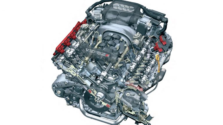
Audi’s BXA engine was a 5.2-litre V10 petrol engine that powered the Audi C6 S6 from 2006 to 2011. The BXA engine was developed from Audi’s 4.2 V8 FSI engine, but had a new crankshaft, balance shaft, double-chambered intake manifold with dual throttle valves and exhaust manifold. Although the BXA engine was similar in design to the Lamborghini Gallardo‘s 5.0-litre V10 engine, Audi’s 5.2-litre V10 engine had:
- Wider bores (84.5 mm compared to 82.5);
- Increased cylinder spacing (90 mm compared to 88 mm);
- Greater displacement (5204 cc compared to 4961 cc); and,
- A higher compression ratio (12.5:1 compared to 11.0:1).
According to Audi, it decided to develop the 5.2 FSI V10 engine rather than a V8 of similar capacity because the former’s lighter pistons and connecting would provide a more free-revving character. Key features of the 5.2-litre BXA engine included its:
- 90-degree ‘V’ angle;
- Aluminium-silicon alloy crankcase and bedplate;
- Forged crankshaft and connecting rods;
- Chain-driven double overhead camshafts with variable intake and exhaust valve timing;
- Variable intake manifold;
- Direct injection (Audi’s ‘Fuel Stratified Injection’ or FSI);
- Bosch MED 9.1 engine management (using a master-slave arrangement); and,
- Euro IV emissions compliance.
The BXA engine was 685 mm long, 801 mm wide and had a mass of 220 kg..
[su_table responsive=”yes”]
| Model | Engine | Trans. | Peak power | Peak torque |
|---|---|---|---|---|
| Audi C6 S6 | 5.2-litre BXA petrol V10 | 6sp auto | 320kW at 6800rpm | 540Nm at 3000-4000rpm |
[/su_table]
Block
The BXA engine had a hypereutectic aluminium-silicon alloy (‘Alusil’, AlSi17Cu4Mg) block that was produced through low-pressure gravity die-casting. Bolted to the bottom of crankcase, the bedplate was cast from AlSi12Cu1 and reinforced with cast-in GGG50 inserts – attached with four screws – that reduced thermal expansion and play in the main crankshaft bearings at high temperatures.
The BXA engine had 84.5 mm bores that were spaced at 90 mm intervals and a 92.8 mm stroke for a capacity of 5204 cc. Furthermore, the cylinder banks had an 18.5 mm offset. Rather than having separate liners, the cylinder bores of the BXA engine were mechanically stripped to separate the aluminium in a three-stage honing and exposure process. By stripping the aluminium from the cylinder surfaces, silicon was exposed in the form of very small and hard particles; these silicon particles were then honed under simulated mechanical stress.
The bare block of the BXA engine had a mass of 47 kg.
Crankshaft, connecting rods and pistons
For the BXA engine, the crankshaft was forged from a hot steel billet in a stamping process. While still hot, the crankshaft was twisted to form the crankshaft throws – this produced a very dense, tough shaft with a grain running in the direction of the principle stress. Furthermore, the shoulder of the connecting rod throws was hardened through an inductive heating method which heated the outer surfaces but not the core.
Due to the engine’s 90-degree ‘V’ angle, the individual crankshaft pins were offset 18 degrees relative to their corresponding opposite cylinders – this ‘split pin’ configuration resulted in an ignition interval of 72 degrees.
The BXA engine had trapezoidal connecting rods that were forged from 36MnVS4 high-strength steel. The lower ends of the connecting rods were cracked after forging so that the breaking surface could be used for high joining precision of the two mating parts. Furthermore, the connecting rods were cross-drilled so that engine oil could lubricate the rod bearings and piston pins.
The cast aluminium pistons were manufactured by Kolben Schmidt and had a special head design for FSI combustion that assisted the tumble effect of the fuel mixture during the intake stroke. The piston skirts were electro-coated with a special iron-based friction-reducing material to reduce wear under load. For cooling, the underside of the pistons and piston pins were sprayed with oil from spray jets.
Balance shaft and vibration damper
The BXA engine had a nodular cast iron balance shaft that was located in the ‘V’ section of the upper crankcase housing between the cylinder banks. The balance shaft rotated in the opposite direction to the crankshaft and at the same speed to offset first order inertia forces.
A vibration damper was fitted at the front of the engine to absorb crankshaft torsional vibrations created during the power stroke. The damper had three main components:
- A counterweight to the crankshaft;
- An accessory drive pulley; and,
- A bonded element (elastomer rubber) that joins the two pieces together.
Viscous oil was used to dampen the relative movement between the elastomer rubber element and the accessory drive pulley – this reduced torsional stress on the crankshaft during combustion and reduces stress to the crankshaft from accessory components driven by the poly-V belt.
Cylinder head
The BXA engine had an aluminium alloy cylinder head with hollow double overhead camshafts per cylinder bank; the cam lobes were attached using a high-pressure water injection process. The camshafts lobes were mated to the camshaft by a hydro-forming process during assembly and actuated the four valves per cylinder by roller finger cam followers; for heat dissipation, the stems of the exhaust valves were filled with sodium. Furthermore, the roller finger cam followers had automatic hydraulic valve clearance adjustment.
The chain-driven camshafts were supported by one-piece, die-cast aluminium ladder bearing frames that were machined after their assembly with the cylinder heads to produce flat axial sealing surfaces between the cylinder head covers, the ladder bearing frames and the attached modular housings.
Variable camshaft timing
The BXA engine had variable intake and exhaust camshaft timing over a range of 42 degrees relative to the crankshaft. The adjusters were hydraulically controlled, but were mechanically locked into place until sufficient oil pressure was developed. The adjustment range of the camshafts is 42 degrees.
Chain drive
The chain drive system for the BXA engine used four 3/8″ simplex roller chains that were mounted on the flywheel side of the engine. Specifically,
- Roller chain A distributed power from the crankshaft to two intermediate sprockets;
- Roller chains B and C distributed power from these sprockets through additional sprockets to the camshafts; and,
- Roller chain D was driven by the crankshaft and drove the engine oil pump, water pump, A/C compressor, power steering pump and the balance shaft.
All chains were tensioned by hydraulic tensioners.
Cooling
The BXA engine had a longitudinal-flow cooling system whereby coolant flowed through the engine block and around the cylinders, upwards into the cylinder head and then longitudinally toward the back of the engine through the chain housing cover. The cooling system was electronically-controlled to regulate the temperature of the coolant between 90 degrees Celsius and 105 degrees Celsius. According to coolant temperature and the position of the thermostat, the cooling system could be divided into large and small circuits whereby coolant was circulated either to the radiator (when the engine was fully warmed) or through the small circuit (when the engine was cold or warming up).
Intake, manifold flaps and variable intake manifold
The BXA engine had a dual intake air system with two air filter housings were mounted on each bank of cylinders. Each intake tract had a 68 mm throttle valve body, while a mass airflow sensor was positioned in the air filter housing.
Within the air filter housing, the BXA engine had intake manifold flaps that were map-controlled by the Engine Control Module. At lower engine loads and speeds, the flaps were brought into contact with the port baffles to seal the lower part of the intake port. As a result, the intake air flowed through the upper section of the intake port and induced a tumbling motion inside the cylinder. When not activated, the intake manifold flaps were in the ‘open’ position which maximised the cross-sectional area of the intake port to reduce intake resistance at higher engine speeds.
The BXA engine had a variable (or ‘dual path’) intake manifold that was made of cast magnesium. Within the upper part of intake manifold, change-over flaps could direct the air through either a long or short intake path according to engine load and speed. The change-over was map-controlled by the engine control module (ECM) and actuated by the variable intake manifold runner motor. The long runner path was 675 mm long and provided better cylinder filling.
For low loads, the short intake runner path was used for engine speeds up to 1000 rpm and beyond 4000 rpm. For high loads, the long intake runner path was used for engine speeds up to 4500 rpm and the short path for higher speeds.
Lubrication
Unlike the Lamborghini Gallardo‘s V10 engine which had dry sump lubrication, the BXA engine had a conventional wet sump. The oil supply system for the BXA engine was designed to minimise the oil flow rate through tighter bearing tolerances. By reducing the flow rate, the oil remained in the sump longer and was better able to recover from aeration; the low flow rate also helped minimise oil pump drive power requirements. According to Audi, at an oil temperature of 120 degrees Celsius, the oil flow rate was 55 litres per minute at 7000 rpm.
Fuel Stratified Injection (FSI)
The fuel system for the BXA engine consisted of a low-pressure circuit which used an electric transfer fuel pump and a high-pressure circuit which used two high pressure fuel pumps (one for each cylinder bank).
The single piston, high-pressure pumps were driven by special lobes on the intake valve camshafts and raised fuel pressure from approximately 6.0 bar (87 psi) to approximately 100 bar (1450 psi). Both high-pressure fuel pumps delivered fuel into a common line to the fuel rails (to reduce pulsation of the fuel), with fuel delivery timed such that the pressure impulses of the pumps were offset at the common rail to minimise pulsations.
Fuel was injected into the cylinders by single-hole sequential fuel injectors that were installed at an angle of 7.5 degrees so that the injection stream was not aimed at the cylinder walls. Upon injection, the evaporation of the fuel in the combustion chamber extracted heat from the cylinders – this reduced knock sensitivity and enabled a compression ratio of 12.5:1.
Ignition
The BXA engine had mapped direct ignition with centrally-mounted spark plugs and ten direct-acting single spark coils. The injection and ignition process was controlled by two Bosch Motronic MED 9.1.1 control modules in a master and slave arrangement that communicated with each other over a private CAN-bus. The firing order of the BXA engine was 1-6-5-10-2-7-3-8-4-9.
Exhaust
As a 90 degree V10 engine, each cylinder bank of the BXA engine had an interval of 144 degrees between adjacent cylinder ignition points which resulted in exhaust opening periods of 210 degrees and partial overlap between the exhaust phases. To prevent reverse pulsation of expelled exhaust gases in the still-open exhaust port, the exhaust manifold had a 2-1-2 manifold runner design. As such, the exhaust ports for each bank of five cylinders was joined to three exhaust manifold runners, with the mating of the exhaust runners for the cylinders was determined by their sequence in the firing order. Specifically,
- On the left bank, the runners for cylinders 6 and 7 were joined into one exhaust runner, while cylinders 9 and ten were joined into another; the exhaust port for cylinder 8 was a separate runner. The manifold runners for cylinders 6, 7 and 8 were then joined to one catalytic converter while the exhaust runners for cylinders 9 and 10 were joined to another; and,
- On the right bank, the runners for cylinders 1 and 2 were joined into one exhaust runner, while cylinders 4 and 5 were joined into another. The exhaust port for cylinder 3 was a separate runner. The manifold runners for cylinders 1, 2 and 3 were joined to one catalytic converter, while the exhaust runners for cylinders 4 and 5 were joined to another.
Emissions control and secondary air injection
The BXA engine had four main ceramic catalytic converters for exhaust gas treatment. Because the two catalytic converters for each bank serviced unequal numbers of cylinders, they were of different sizes.
The BXA engine had a secondary air injection system so that the catalytic converters reached their operating temperature faster. In this process, the fuel mixture was enriched to produce a higher percentage of unburnt hydrocarbons in the exhaust gas. The secondary air injection – located downstream of the exhaust valves – then enriched the exhaust gases with oxygen, causing oxidation (i.e. after-burning) of the hydrocarbons and carbon monoxide.
Crankcase ventilation and breather
The BXA engine had a crankcase ventilation system that recycled unburnt hydrocarbons (blow-by gases) for combustion so that they did not escape into the outside air. Each cylinder head cover had channels cast in its housing to direct blow-by gases from the crankcase to a cyclone fine oil separator; the channels also allowed some of the oil mixed with blow-by gases to return to the crankcase by gravity. The blow-by gases were then directed from the cylinder head covers to the fine oil separator by a plastic hose. The fine oil separator had three cyclone oil separators and consisted of a control piston, bypass valve, two-stage pressure limiting valve and an oil return valve. After the blow-by gases had passed through the fine oil separator, they flowed into the intake manifold downstream of the throttle bodies.
The crankcase ventilation system included a crankcase breather which drew air from the air filter box so that it flowed through a check valve into the crankcase at the engine’s inner ‘V’. The mixture of fresh air helped reduce the water and fuel mixture in the crankcase from the blow-by gases.


