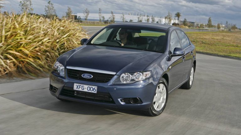
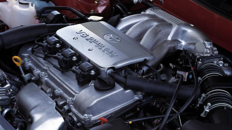
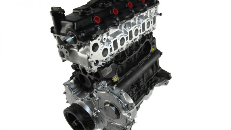
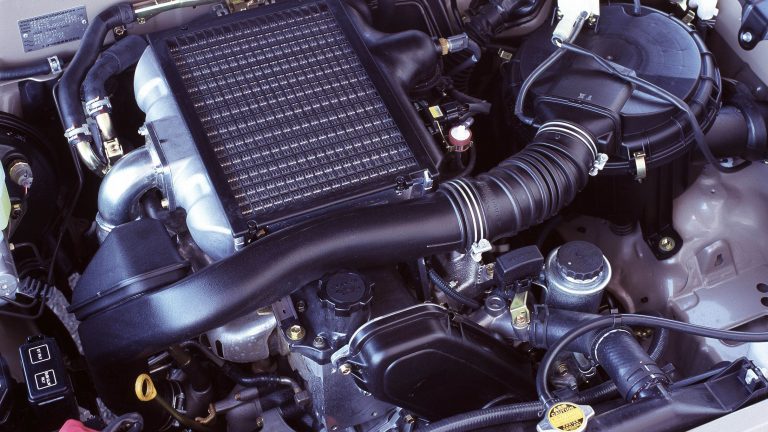
[su_image_carousel source=”media: 51321,51322,51323,51324,51325,51326,51327″]
Introduction
Ford’s Barra 195 was a naturally aspirated, 4.0-litre inline six-cylinder petrol engine that was introduced in the Ford FG Falcon in 2008. Replacing Ford’s Barra 190 engine, changes for the Barra 195 included:
- A redesigned cylinder head; and,
- A new split plenum intake manifold.
On 90 RON regular unleaded petrol, the Barra 195 engine produced peak power and torque of 195 kW at 6000 rpm and 391 Nm at 3250 rpm, respectively. On 95 RON unleaded petrol, however, peak outputs increased to 198 kW and 409 Nm.
[su_table responsive=”yes”]
| Model | Engine | Trans. | Peak power | Peak torque | Years |
|---|---|---|---|---|---|
| Ford FG Falcon | 4.0-litre petrol I6 | 6sp man., 5sp auto, 6sp auto |
195kW at 6000rpm | 391Nm at 3250rpm | 2008-14 |
| Ford FG X Falcon | 4.0-litre petrol I6 | 6sp man., 6sp auto |
195kW at 6000rpm | 391Nm at 3250rpm | 2011-16 |
| Ford SZ Territory | 4.0-litre petrol I6 | 6sp auto | 195kW at 6000rpm | 391Nm at 3250rpm | 2014-16 |
[/su_table]
Block
Like Ford’s other Barra engines, the Barra 195 engine had a cast iron block with 92.26 mm bores and a 99.31 mm stroke for a capacity of 3984 cc. Similarly, the Barra 195 block had cross-bolted main bearing caps to increase rigidity and a cross-bolted alloy sump.
Cylinder head
The Barra 195 engine had a gravity-cast, aluminium alloy cylinder head which was mounted on a single layer steel (SLS) sheet metal gasket. For the Barra 195 engine, a redesigned ‘fast burn’ cylinder head was introduced which had revised intake port profiling and new combustion chamber geometry to increase swirl for faster combustion. According to Ford, the higher turbulence enabled additional camshaft retard at part throttle due to an improved lean limit, thereby reducing pumping losses and improving fuel efficiency.
The water jacket for the Barra 195 engine featured deflection vanes to squeeze coolant past hot spots – such as the exhaust valve seats – at higher velocities to achieve more even temperatures throughout the cylinder head.
Camshafts and valvetrain
The Barra 195 engine had double overhead camshafts that were driven by a single-stage roller chain. To minimise weight and improve durability at higher engine speeds, the camshafts were roll-forged and had bored centres.
The Barra 195 engine had four valves per cylinder that were actuated by roller finger followers; hydraulic lash adjusters maintained zero valve clearance, while a clip held the lash adjuster to the rocker for durability. To limit in-chamber tumble and provide good seating, the valves had a domed head and no lip. Valvetrain specifications for the Barra 195 – given in the table below – are understood to be the same as the Barra 190 engine.
[su_table responsive=”yes”]
[/su_table] Dual Independent Variable Cam Timing (DI-VCT)The Barra 195 engine had a vane-type VCT phaser – produced by Aisin – on each camshaft that provided continual variable adjustment within a 60 degree range (10 degrees advanced or 50 degrees retarded from the initial pin lock position). Each camshaft phaser was hydraulically controlled via an oil control valve that was mounted on top of it. The variable cam timing system for the Barra 195 engine was Ford’s ‘Dual Independent Phase Shifting’ (DIPS) which enabled the intake and exhaust camshafts to be varied independently of each other. In contrast, the Barra 182 engine had Dual Equal Phase Shifting (DEPS) in which the intake and exhaust camshafts could only be advanced or retarded by the same degree synchronously such that valve overlap was a constant 25 degrees. Valve timing for the Barra 195 engine is understood to be the same as the Barra 190 engine and is given in the tables below. From these, valve overlap could be varied from -35 degrees to 85 degrees, intake duration was 256 degrees and exhaust duration was 256 degrees. Furthermore,
[/su_table]
[/su_table]
[/su_table] IntakeThe Barra 195 engine introduced a new ‘dual mode, split plenum intake manifold’. The purpose of the split plenum intake manifold was to separate intake pulses in the manifold according to the firing order of the cylinders – this minimised interference of one cylinder’s pressure waves with those of another, improving mid-range torque. It is understood that the term ‘dual mode’ was used to refer Ford’s ‘Intake Manifold Charge Control’ or IMCC system which used a butterfly valve in the intake runner for each cylinder that was controlled by the Powertrain Control Module (PCM) via a vacuum actuator. In normal operation, the butterfly valves were closed to create a longer intake path to increase the pulsing effect of the intake air, draw more air into the cylinder and increase torque. At higher engine speeds (i.e. above approximately 3800 rpm for the Barra 182 and Barra 190), the butterfly valves would to create a shorter intake path which reduced intake resistance and allowed a greater volume of air into the cylinder for top-end power. The Barra 195 intake manifold incorporated a new throttle body and fuel rail assembly; like the Barra 182 and Barra 190, the Barra 195 engine had electronic ‘drive-by-wire’ throttle control. Furthermore, the intake manifold was made of composite materials, including glass fibre reinforced nylon (30 per cent grade), to achieve a 4 kg mass reduction. For the Barra 195 engine, the airbox and intake duct surfaces were stiffened and ribbed to minimise the transmission of air flow noise, while four resonators were tuned to remove intake system resonance noise. Injection and ignitionThe Barra 195 engine had an electronically-controlled sequential fuel injection. The ‘speed density’ fuel injection system used the engine speed, intake air temperature and manifold absolute pressure sensors to calculate intake air mass and therefore the fuel required to be injected for combustion. This quantity of fuel was then adjusted according to feedback information from the Heated Oxygen (HEGO) sensor, providing close loop control of fuel injection. The Barra 195 engine had distributorless, coil-on-plug ignition with individual coils mounted above the spark plug. The long-life spark plug was positioned in the centre of the combustion chamber roof between the four valves. Like the Barra 190 engine, each spark plug had a 0.5 mm finewire centre electrode and platinum pad ground electrodes. As introduced in the Barra 190, the ignition system for the Barra 195 featured adaptive and variable dwell (the time required to charge the ignition coil) for more efficient ignition control. Specifically,
The Barra 195 engine had a compression ratio of 10.3:1 and 1-5-3-6-2-4 firing order. Knock sensing and spark correctionLike the Barra 190, the Barra 195 engine had twin knock sensors which, according to Ford, enabled a change in ignition timing strategy for more accurate spark control, improved fuel economy and greater refinement. Specifically, the Powertrain Control Module had four forms of spark control:
If using premium unleaded petrol, spark advance enabled greater power and lower fuel consumption. Back To Top
| |||||||||||||||||||||||||||||||||||||||||||||||||||


