[su_image_carousel source=”media: 51710,51689,51690,51691,51692,51693″]
Introduction
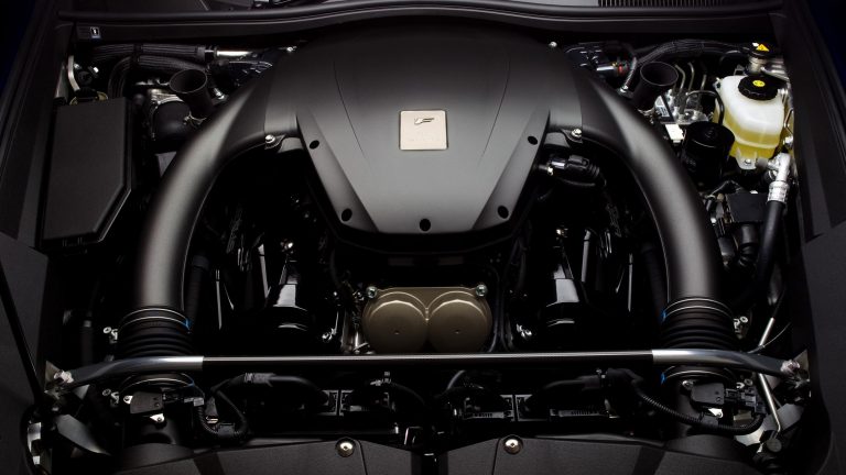
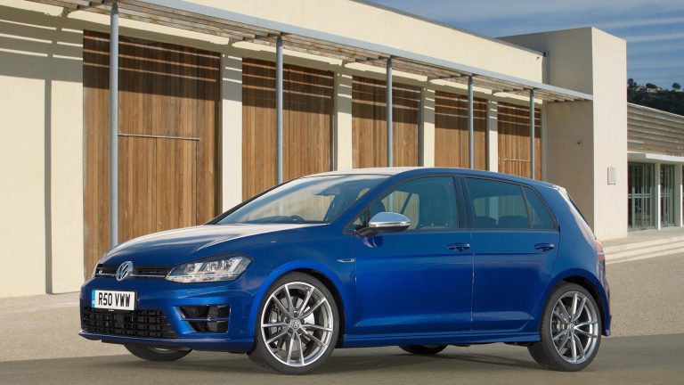
The VW Mk.7 Golf R was powered by Volkswagen’s CJXB and CJXC engines; these 2.0-litre turbocharged petrol engines were members of Volkswagen’s EA888 Gen 3 engine family. Compared to the CCHA/CHHB engines in the Volkswagen Mk.7 Golf GTi, changes for the CJXB/CJXC engines in the Mk.7 Golf R included:
- A different alloy for the cylinder head due to higher thermal stress;
- The exhaust valves were nitrided and had a higher Ni content;
- The exhaust valve seat rings were upgraded for improved temperature stability and wear resistance;
- Revised exhaust camshaft timing;
- A larger IHI turbocharger which provided peak boost pressure of 1.2 bar (17.4 psi);
- Unique pistons for a 9.3:1 compression ratio (compared to 9.6:1);
- For the piston cooling jets, a higher flow rate;
- For the high pressure injectors, a higher flow rate; and,
- A high performance main radiator with one or two auxiliary radiators (depending on market).
[su_table responsive=”yes”]
| Model | Engine | Trans. | Peak power | Peak torque |
|---|---|---|---|---|
| Volkswagen Mk.7 Golf R (Australia) | 2.0-litre CJXB turbo petrol I4 | 6sp man. | 206kW at 5100-6500rpm | 380Nm at 1800-5500rpm |
| Volkswagen Mk.7 Golf R | 2.0-litre CJXC turbo petrol I4 | 6sp man. | 221kW at 5500-6200rpm | 380Nm at 1800-5500rpm |
[/su_table]
Block
The EA888 Gen 3 engine had a closed-deck, grey cast iron (GJL 250) block with 82.5 mm bores and a 92.8 mm stroke for a capacity of 1984 cc. For the EA888 Gen 3 engine,
- The casting process was changed from conventional flat pouring to upright pouring; and,
- Nominal cylinder wall thickness was reduced from 3.5 +/- 0.8 mm to 3.0 +/- 0.5 mm.
Within the cylinder block, the EA888 Gen 3 engine had two balance shafts to counteract second degree inertial forces. The horizontally-staggered balance shafts rotated at twice the engine speed in opposite directions from one another, with the direction of the second shaft reversed by an idler gear. The balance shafts were made from spheroidal graphite cast iron and, for the EA888 Gen 3 engine, lower-friction roller bearings were introduced.
Crankshaft, connecting rods and pistons
The EA888 Gen 3 engine had a forged steel crankshaft that was induction hardened and had four counterweights. The crankshaft for the CJXB/CJXC engines operated on five main bearings which had a diameter of 48 mm.
It is understood that the connecting rods for the CJXB/CJXC engines were made from 36MnVS4 and were cracked for precision fitting and reduce movement of the bearing cap under load.
For the EA888 Gen 3 engine, a new ‘strength-enhanced alloy’ piston coating was applied. Furthermore, an electric system was introduced to control the oil-jet cooling for the pistons.
Cylinder head
The EA888 Gen 3 engine is understood to have a cross-flow cylinder head that was made of AlSi10Mg and mounted on a three-layer metal head gasket. In a new development, however, the exhaust manifold for the EA888 Gen 3 engine was integrated into the cylinder head. Furthermore, the cylinder head had a fully integrated water-cooled exhaust gas circulation loop so that full load enrichment (i.e. enriching the fuel/air mix at higher loads) was no longer required for cooling, thereby improving fuel consumption at high loads.
Camshafts and valves
The EA888 Gen 3 engine had hydro-formed, double overhead camshafts that were driven by gear chains (as opposed to roller chains). For the EA888 Gen 3 engine, the intake and exhaust valves were actuated by roller cam followers with needle bearings and hydraulic valve clearance adjusters. It is understood that both the intake and exhaust valves were chrome-plated and had reinforced seats. While the intake valves had solid stems, the exhaust valves were also tempered and had sodium-filled stems for heat dissipation.
Variable valve timing and exhaust valve lift
The EA888 Gen 3 engine had variable intake and exhaust valve timing as well as variable exhaust valve for better control of the charge exchange process.The variable exhaust valve lift system is understood to be based on the ‘Audi Valve Lift System’ (AVS) whereby the camshaft had two valve lift contours for each exhaust valve (small and large). In this system, change-over between the cam lobe contours was achieved by the longitudinal displacement of the cam elements via electromagnetic solenoid-type actuators. One actuator moved the cam element on the camshaft for large valve lift, while the other actuator reset the cam element for small valve lift.
At low engine speeds (up to around 3100 rpm), the small profile cam lobe contour was used to:
- Provide late exhaust valve opening;
- Prevent the back-flow of exhaust gas during the valve overlap phase; and,
- Enable advanced intake valve timing.
Specifically, the positive cylinder pressure gradient allowed the combustion chamber to be effectively purged – this enhanced fuel/air mixture formation by reducing the residual gas content in the cylinder and enabled advanced intake valve timing since less intake air was expelled after BDC (bottom dead centre). As a result, greater torque was produced at low engine speeds and charge pressure could be accumulated faster.
At high engine speeds, the large profile cam lobe contour was used.
The intake camshaft could be continuously adjusted over a range of 30 degrees relative to the crankshaft, while the exhaust camshaft could be adjusted over a range of 60 degrees.
IHI turbocharger
The CJXB/CJXC engines have an IHI turbocharger which is integrated with the exhaust manifold and provides peak boost pressure of 1.2 bar (17.4 psi). Like the Mk.7 Golf GTi’s CHHA/CHHB engines, the IHI turbocharger for the CJXB/CJXC engines is understood to feature:
- A new alloy for the turbine wheel that can withstand exhaust gas temperatures up to 980 degrees Celsius;
- A new electric wastegate actuator that reduces boost pressure when the power is not needed to reduce fuel consumption;
- The fitment of pulsation damper; and,
- The addition of an oxygen sensor mounted directly upstream of the turbine wheel.
[su_table responsive=”yes”]
| CJXB/CJXC EA888 Gen 3: IHI turbocharger | ||
|---|---|---|
| Turbine | Blade diameter (inducer/exducer) | 47.4 mm / 54.7 mm |
| Number of blades | 8 | |
| Compressor | Blade diameter (inducer/exducer) | 45.2 mm / 58.0 mm |
| Number of blades | 6 + 6 | |
[/su_table]
Cooling
The EA888 Gen 3 engine introduced a fully-electronic coolant control system for more efficient thermal management. The system included a new type of rotary vane module that could block coolant entry into the engine or adjust to low volumetric flows in the engine’s warm-up phase. As a result, shorter warm-up times were achieved, thereby reducing frictional losses and improving fuel economy. At higher engine temperatures, coolant temperature could be adjusted quickly and variably as a function of engine load and external constraints.
Port and direct injection
The EA888 Gen 3 engine has both direct and port fuel injection via separate sets of injectors. The EA888 Gen 3 engine adopted a dual injection system to reduce particulate emissions and comply with Euro 6 emissions standards.
Based on inputs from sensors, the engine management system controlled the injection volume and timing of each type of fuel injector, according to engine load and engine speed, to optimise the fuel:air mixture for engine conditions. The injection system is understood to have the following operating conditions:
- Cold start: the port injectors provided a homogeneous air:fuel mixture in the combustion chamber, though the mixture around the spark plugs was stratified by compression stroke injection from the direct injectors. Furthermore, ignition timing was retarded to raise exhaust gas temperatures so that the catalytic converter could reach operating temperature more quickly;
- Low engine speeds: port injection and direct injection for a homogenous air:fuel mixture to stabilise combustion, improve fuel efficiency and reduce emissions; and,
- Medium to high engine speeds and loads: direct injection only to utilise the cooling effect of the fuel evaporating as it entered the combustion chamber to increase intake air volume and charging efficiency.
Ignition
The CJXB/CJXC engines had four single spark ignition coils and cylinder-selective anti-knock control. Furthermore, the CJXB/CJXC engines had a 1-3-4-2 firing order and compression ratio of 9.3:1.