[su_image_carousel source=”media: 52010,52011,52012,52013,52014,52015,52016″]
Introduction
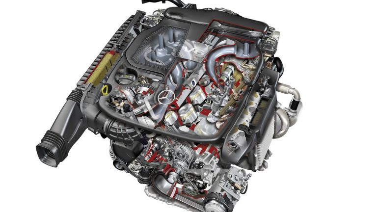
Available from 2011, the Mercedes-Benz M276 engine was a 60-degree V6 petrol engine that replaced M272 engine. Manufactured at Mercedes-Benz’s Stuttgart-Bad Canstatt engine plant and developed in conjunction with M278 V8 engine, key attributes of the M276 engine included its:
- aluminium alloy cylinder block and head;
- third-generation direct injection system with electronically-controlled piezo injectors;
- multi-spark ignition (i.e. multiple ignition events during the combustion stroke);
- double overhead camshafts (chain-driven) with independent intake and exhaust camshaft adjustment; and,
- ECO start/stop system.
Initially, the M276 DES 35 engine had 92.9 mm bores and an 86.0 mm stroke for a capacity 3498 cc – these engines were naturally aspirated and had compression ratios of 12.2:1. In 2013, the M276 DEH 30 LA engine was released – it had a capacity of 2996 cc with 88.0 mm bores and an 82.1 mm stroke. Significantly, the M276 DEH 30 LA engine had an IHI turbocharger fitted to each cylinder bank which provided peak boost pressure of 1.8 bar (26.1 psi); the compression ratio was also lowered to 10.7:1.
In September 2014, the M276 DES 35 LA engine was released – it was a biturbo version of the M276 DES 35 engine which produced 245 kW at 5250-6000 rpm (the same as the M276 DE 30 AL) and 480 Nm at 1200-4000 rpm (peak torque achieved 200 rpm lower than the M276 DE 30 AL).
Crankcase
The M276 engine had an aluminium alloy crankcase and, initially, cast iron cylinder liners. In early 2013, however, Mercedes-Benz’s ‘Nanoslide’ cylinder wall coating was introduced. Based on an iron-carbon alloy, the Nanoslide carbon was applied through twin-wire arc spraying (TWAS). Since the Nanoslide coating produced a microporous surface for the cylinder walls, effective lubrication was achieved without the need for cast-iron cylinder liners. According to Mercedes-Benz, the Nanoslide coating reduced friction between the piston, piston rings and cylinder wall by up to 50 per cent and achieved a mass reduction of several kilograms.
To ventilate the crankcase, there was a ventilation line with restrictor and check valve integrated between the air filter and the left cylinder head. In contrast to the M272 engine, the M276 engine only had one oil separator in the vent line; the centrifuge at the rear of the right cylinder head, however, was the same as previously. In all load states, the engine was vented via the pressure regulating valve starting at the centrifuge.
Since the M276 engine had a 60-degree ‘V’ configuration, it did not require a balance shaft. Other mass reduction measures included the replacement of aluminium and steel materials by plastics for components such as the thermostat, belt pulley, wheel, heater valve and hydraulic lines.
Cylinder head
The M276 engine had an aluminium alloy cylinder head with a two-piece water jacket and cooling slot between the cylinders.
For the double overhead camshafts, the M276 engine had a two-stage chain drive with three gear chains, each of which was tensioned by a hydraulic tensioner. The M276 engine had hydraulic vane-cell camshaft adjusters with integrated control valve for fast and stepless operation. The camshaft adjuster was capable of adjusting all four camshafts steplessly by up to 40 crank angle degrees (i.e. relative to the crankshaft) to vary valve overlap. Intake valve opening (IO) could be varied from 4 degrees BTDC to 36 degrees ATDC, while exhaust valve closing (EC) could be varied from 25 degrees BTDC to 15 degrees ATDC. On start-up, the camshafts were locked in a fixed position by a catch bolt and this start position was unlocked hydraulically the first time the intake camshaft and exhaust camshaft solenoids were actuated.
The M276 engine had four valves per cylinder – two intake and two exhaust – that were actuated by roller cam followers.
Variable intake manifold
Naturally aspirated versions of the M276 engine had a variable intake manifold. For the M276 engine, the right and left sides of the intake manifold were connected via a resonance chamber. The effective length of the intake manifold was changed by the operation of resonance flaps and a selector drum –
- At engine speeds below 3200 rpm and engine loads below 50 per cent, the resonance flaps were closed so air from the intake manifold would be directed behind the cylinders for the longest possible path;
- At engine speeds from 3200-4250 rpm and engine loads above 50 per cent, the resonance flaps opened and intake air could flow via the resonance chamber between the right and left intake tracts of the intake manifold for greater throughput; and,
- At engine speeds above 4250 rpm and engine loads above 50 per cent, the selector drum that was positioned between the cylinder banks opened. When this occurred, intake air would flow through the selector drum (i.e. through the centre of the intake manifold) and the rear tracts of the intake manifold were closed.
Fuel supply
For the naturally aspirated M276 engine, fuel pressure from the low-pressure fuel pump varied from approximately 4.5 to 6.7 bar depending on the requirements. When actuated, the fuel pump drew fuel from the fuel feed module and pumped it through the fuel filter; at a pressure of 7 to 9 bar, the overflow valve in the fuel filter would open. Fuel from the low-pressure fuel pump distributor would then flow to the high-pressure fuel pump – located at the rear end of the right intake shaft and actuated by three cams – to generate the pressure necessary for spray-guided direct injection. Depending on the operating state, the high-pressure pump would compress the fuel to 120-200 bar depending on operating mode; the fuel would then be directed through the high-pressure line and the fuel rails to the fuel injectors.
Direct injection
The M276 engine had a third-generation direct injection system with a non-return high-pressure supply with two separate fuel rails. From the rail, the piezo injectors sprayed finely atomised fuel into the combustion chambers and were capable of delivering up to five injections per cycle. A coupler module inside each fuel injector ensured that the nozzle module and the piezo actuator module had zero clearance in the longitudinal direction. The fuel feed was sealed on the high-pressure side with an O-ring at the rail. Another O-ring at the fuel injector sealed the leak line. Furthermore, the seal between the fuel injector and the cylinder head was provided by a Teflon ring.
Combustion modes: M276 DEH (homogeneous) and M276 DES (stratified)
The M276 V6 engine was available in two operating variants: the M276 DEH for the USA and the M276 DES for European and rest of world markets –
- The M276 DEH engine had homogeneous combustion in which an air/fuel mixture with a lambda of 1 (i.e. a stoichiometric ratio of 14.7:1) was produced throughout the combustion chamber. This system required no additional exhaust after-treatment measures as the standard three-way catalytic converter could adequately convert pollutants; and,
- For the M276 DES engine, stratified combustion used a combustible mixture that had a lambda approximately equal to 1 only in the vicinity of the spark plug. As such, lambda values in the rest of the combustion chamber could vary, and range from pure intake air to recirculated exhaust gases enriched with intake air to reduce the combustion temperature. While fuel consumption in stratified operation was lower than homogeneous operation, the excess air means that the formation of NOx was significantly higher than in homogeneous combustion. As a result, a NOx storage catalytic converter was required.
In additionto homogenous and stratified charge combustion methods, the M276 DES engine could also utilise Homogenous stratified (HOS) and Homogenous Split (HSP) combustion methods. Of these,
- Homogeneous Stratified combustion was a combination of homogeneous lean-burn and conventional stratified combustion. With Homogenous Stratified combustion, the first injection was sprayed during the intake stroke, forming a homogeneous basic mixture. ‘Stratified’ injection then occurred during the compression stroke before ignition and was a single or double injection depending on the characteristic map; and,
- With Homogenous Split combustion, more than 95 per cent of the fuel was singly or multiply injected, followed by a very small ‘ignition’ injection to stabilise combustion – this mode was used only in high load situations.
The electronic control unit (ECU) for the M276 DES engine applied these combustion methods in the following situations –
- Idling range: homogeneous combustion;
- Low partial loads (up to 4 bar) and up to 3800 rpm: stratified combustion;
- Medium partial loads (4 to 8 bar) and up to 4000 rpm: Homogeneous Stratified, or HOS, combustion; and
- High loads and entire engine speed range: homogeneous lean-burn or Homogeneous Split combustion.
Multi-spark ignition
The M276 engine had single- and multi-spark ignition modes. In the standard single-spark ignition mode, the ignition coil would charge to a target primary current and, at firing point, the charging current would be shut off to produce a spark.
In multi-spark mode, however, the coil would not be completely discharged and the secondary current – which was dependent on the charge level of the coil – would be measured in the coil. If the secondary current dropped below a threshold, the coil’s electronic control would re-open the power amplifier to allow charging current to flow, while the level of the primary current would also monitored. When the primary current threshold was reached, the power amplifier would close the primary circuit and high voltage would be generated again, causing another spark to be produced. Subsequent sparks were also produced in the same manner.
Multi-spark ignition could achieve up to four successive sparks (within one millisecond) to create a plasma which provided greater spatial expansion than conventional ignition. As such, it was possible to use a much leaner mixture with stratified combustion and reduce fuel consumption.
ECO start/stop
The M276 engine had a start-assisted in-engine direct start function and an engine stop function which combined to form a start/stop function. With the selected piezo injection valve coupled with the correct injection timing, the very first compression stroke of a cylinder could be utilised for a controlled combustion. To drive off immediately after a direct start of the engine, however, the oil supply to the transmission hydraulics had to be maintained while the engine was off and while it was being restarted. As such, the additional electric transmission oil pump supplied oil to the transmission control system when the internal transmission pump is off.
The ECO start/stop function also utilised an additional 12 Ah battery which ‘cushioned’ the voltage drop during engine starts. Specifically, the additional battery supplied power to all active consumers while the regular battery was decoupled from the on-board electrical system and made available solely to the starter.
Ancillaries and lubrication
To reduce energy demand, the M276 engine had efficient ancillary units such:
- As an optimised water pump with second generation thermal management;
- A newly developed vane-type oil pump with on-demand quantity control and two map-controlled, switched pressure levels. At the high pressure level, the lubrication and cooling points in the engine were supplied with the maximum quantity of oil at 4 bar. At the low level, however, the flow rate was reduced to 2 bar and the oil sprayers for cooling the piston undersides were also shut off;
- Volume-controlled high-pressure fuel pump; and,
- A variable alternator.
[su_table responsive=”yes”]
| Engine | Capacity | Peak power | Peak torque | Model | Years |
|---|---|---|---|---|---|
| M276 DE 30 AL | 2996 cc | 245 kW at 5250-6000 rpm | 480 Nm at 1600-4000 rpm | W205 C 400 | 2014-on |
| A207 E 400, C207 E 400 |
2013-16 | ||||
| W212 E 400 | 2013-14 | ||||
| W222 S 500 Plug-in Hybrid | 2014-on | ||||
| R231 SL 400 | 2014-on | ||||
| M276 DE 35 red. | 3498 cc | 185 kW at 6500 rpm | 340 Nm at 3500-4500 rpm | W166 ML 300 | 2012-on |
| A207/C207 E 300 | 2011-on | ||||
| W212 E 300 | 2011-16 | ||||
| C218 CLS 300 | 2012-on | ||||
| M276 DE 35 | 3498 cc | 225 kW at 6500 rpm | 370 Nm at 3500-5250 rpm | W166 ML 350 | 2011-on |
| R172 SLK 350 | 2011-on | ||||
| W204 C 350 | 2011-14 | ||||
| X204 GLK 350 | 2011-on | ||||
| A207 E 350, C207 E 350 |
2011-16 | ||||
| W212 E 350 | 2011-16 | ||||
| W212 E 400 Hybrid | 2012-16 | ||||
| C218 CLS 350 | 2011-on | ||||
| W221 S 350 | 2011-13 | ||||
| V222 S 400 Hybrid | 2013-on | ||||
| R231 SL 350 | 2012-14 | ||||
| W251 R 350 | 2012-13 | ||||
| M276 DE 35 AL | 3498 cc | 245 kW at 5250-6000 rpm | 480 Nm at 1200-4000 rpm | W212 E 400 | 2014-16 |
| C218 CLS 400 | 2014-on |
[/su_table]


