Introduction
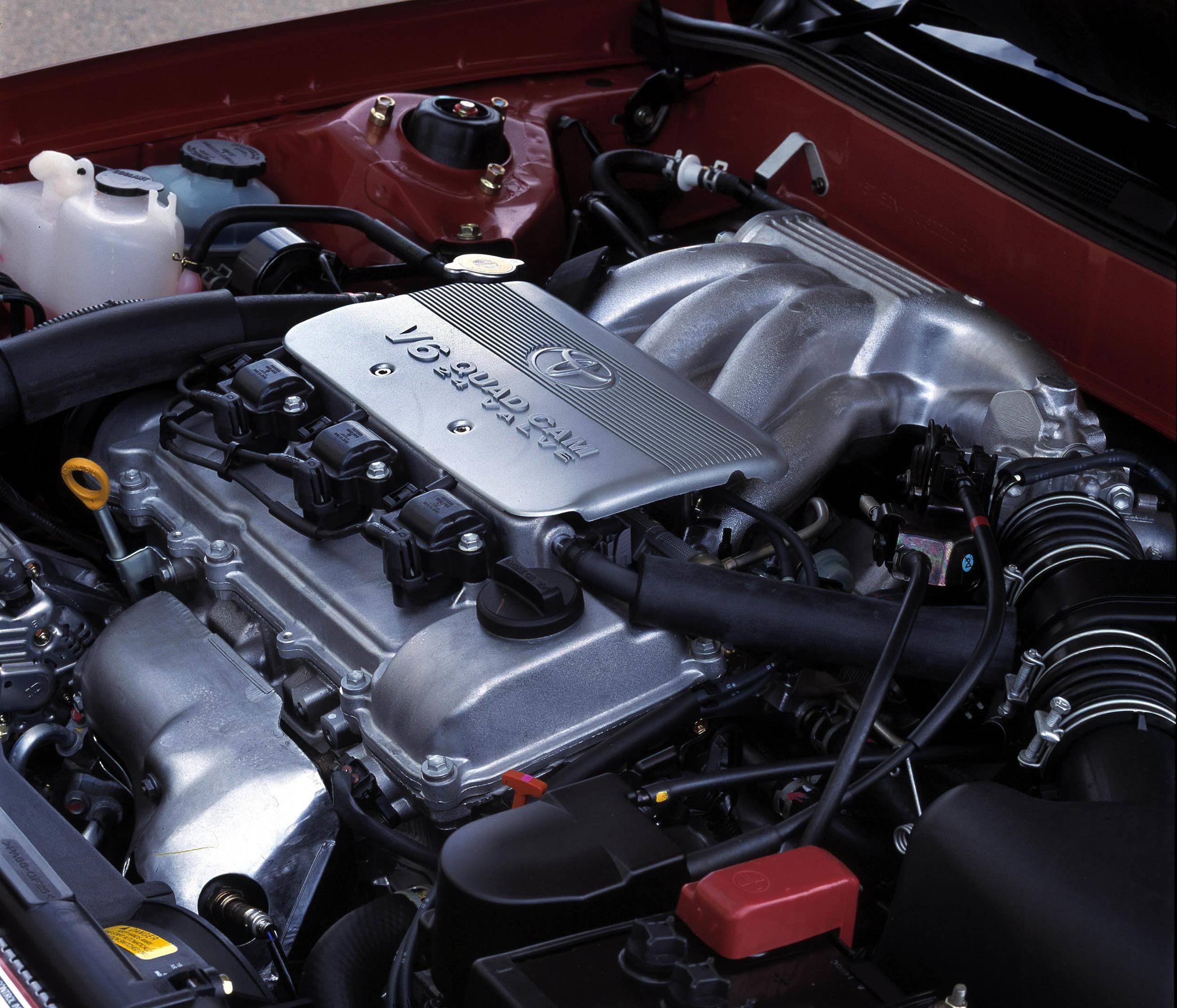
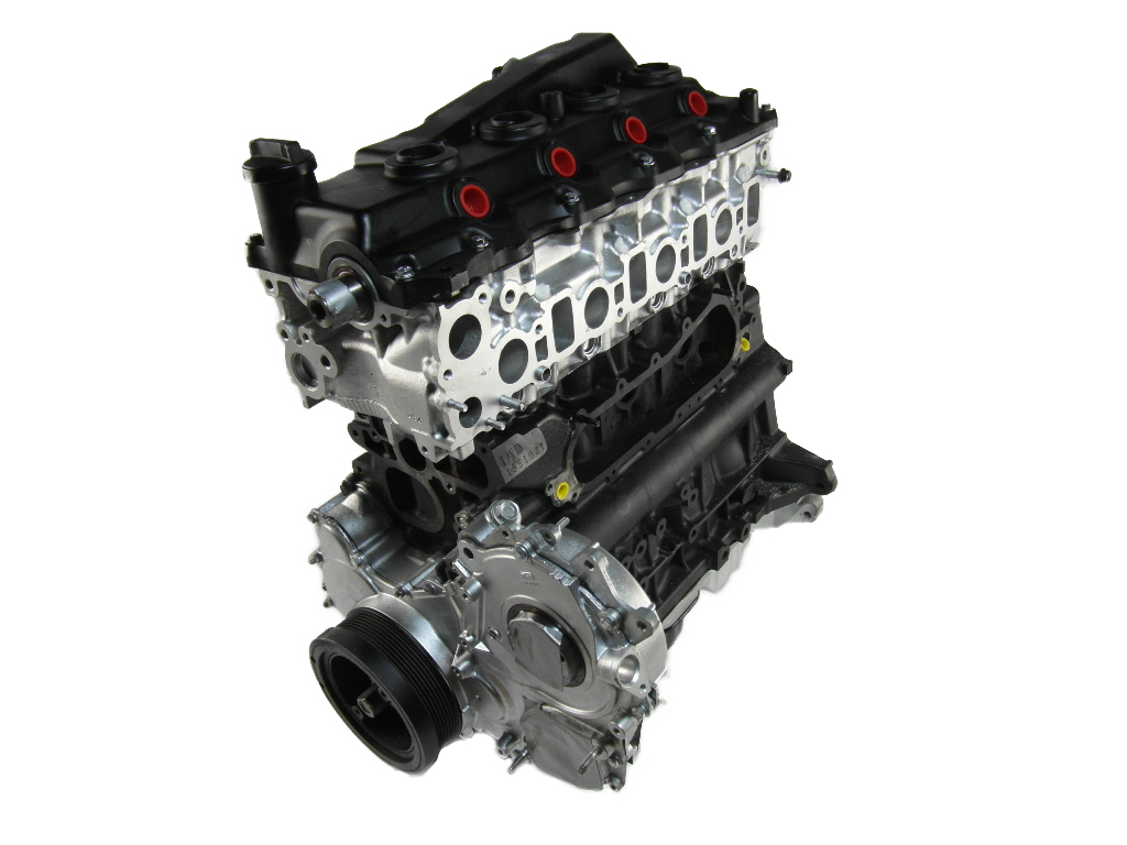
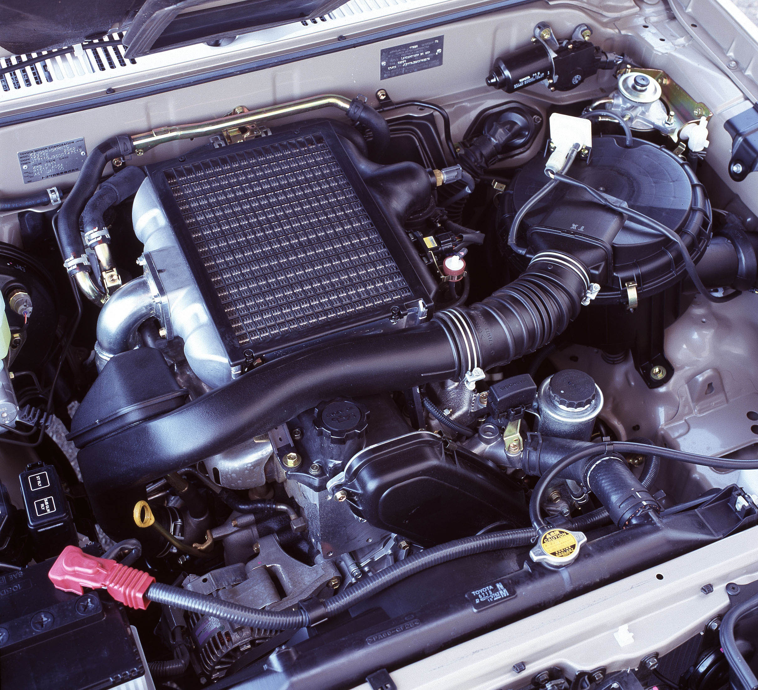
Toyota’s 2TR-FE was a 2.7-litre four-cylinder petrol engine. A member of Toyota’s ‘TR’ engine family, the 2TR-FE effectively replaced the 2.7-litre 3RZ-FE engine and powered the Mk.7 Hilux utility and Mk.5 HiAce van.
| Engine | Trans. | Years | Peak power | Peak torque | |
|---|---|---|---|---|---|
| ToyotaMk.5 HiAce van | 2.7-litre petrol I4 | 5sp man., 4sp auto |
2005-15 | 111kW at 4800rpm | 241Nm at 3800rpm |
| 5sp man., 6sp auto |
2015-on | 118kW at 5200rpm | 243Nm at 4000rpm | ||
| ToyotaMk.7 Hilux | 2.7-litre petrol I4 | 5sp man. | 2005-08 | 118kW at 5200rpm | 241Nm at 3800rpm |
| 5sp man., 4sp auto |
2008-15 | 116kW at 5200rpm | 240Nm at 3800rpm | ||
| ToyotaMk.8 Hilux | 2.7-litre petrol I4 | 5sp man., 6sp auto |
2015-on | 122kW at 5200rpm | 245Nm at 4000rpm |
2TR-FE block and balance shafts
The 2TR-FE had a cast iron, deep-skirt cylinder block with 95.0 mm bores and a 95.0 mm stroke for a capacity of 2694 cc.
The 2TR-FE had twin counter-rotating balance shafts within the crankcase to cancel the secondary inertia forces that were inherent in an in-line four-cylinder engine. Since each piston reached its maximum speed – both rising and falling – at a point just above the centre of the stroke, the upward inertial force of the two rising pistons was greater than the downward inertial force of the two falling pistons. To offset this, the twin gear-driven balance shafts counter-rotated at twice the speed of the crankshaft.
Crankshaft, connecting rods and pistons
The 2TR-FE engine had a fully-balanced crankshaft with roll-finished pin and journal fillets. To reduce noise, vibration and harshness (NVH), the crankshaft pulley had a torsional rubber damper.
The high strength connecting rods had plastic-region tightening big-end bolts to maximise clamping force. To improve oil clearance and hence cold-cranking performance, the upper bearing shells had an oil groove and the lining surface of the bearings had micro grooves.
The 2TR-FE engine had aluminium alloy pistons that were cooled by oil jets at the bottom of the cylinder bores. To reduce friction and improve wear resistance, the piston skirts had a resin coating, while the groove of the top piston ring was coated with alumite (anodic oxide coating) for abrasion resistance. Furthermore, the no.1 compression ring had a Physical Vapor Deposition (PVD) coating for wear resistance and the no.2 piston ring was chrome plated.
Cylinder head and camshafts
The 2TR-FE engine had an aluminium alloy cylinder head with double overhead camshafts. The camshafts were hollow and driven by a roller chain which had a 9.525 mm chain and was lubricated by an oil jet. The chain tensioner used a spring and oil pressure to maintain chain tension, and suppressed noise generated by the timing chain.
Valves
The 2TR-FE engine had four valves per cylinder – two intake and two exhaust – that were positioned for a 22.85 degree included valve angle. The valves were actuated by roller rocker arms which had built-in needle bearings to reduce friction between the cams and roller rocker arms.
At the fulcrum of each roller rocker arm there was a hydraulic lash adjuster which consisted of a plunger, plunger spring, check ball and check ball spring. The oil pressure and the spring force that acted on the plunger pushed the roller rocker arm against the cam to adjust the valve clearance that was created during the opening and closing of the valve. As a result, the hydraulic lash adjusters maintained constant zero valve clearance.
Variable Valve Timing – intelligent (VVT-i)
For the 2TR-FE engine, Toyota’s ‘variable valve timing with intelligence’ (VVT-i) varied the intake camshaft over a range of 45 degrees (relative to crankshaft angle) according to engine speed, throttle position, inlet camshaft angle, engine coolant temperature and intake air volume.
The VVT-i controller consisted of the housing driven from the timing chain and the vane coupled with the intake camshaft. The camshaft timing oil control valve controlled the spool valve using duty-cycle control from the ECU. The oil pressure sent from the advance or retard side path at the intake camshaft caused rotation in the VVT-i controller vane circumferential direction to vary intake valve timing continuously. Furthermore, the ECU used signals from the camshaft position sensor and the crankshaft position sensor to detect actual valve timing, thus providing feedback to achieve target valve timing.
When the engine was stopped, the intake camshaft would be in its most retarded state for ease of starting. Since hydraulic pressure was not applied to the VVT-i controller immediately after the engine started, a lock pin would restrict movement of the VVT-i controller to prevent a knocking noise. Once hydraulic pressure was applied to the VVT-i controller, the lock pin was released.
Intake and throttle
The 2TR-FE engine had a plastic intake manifold to reduce mass and limit heat transfer from the cylinder head. In contrast to a conventional throttle which used accelerator pedal effort to determine throttle angle, Toyota’s ‘Electronic Throttle Control System – intelligent’ (ETCS-i) used the ECM to calculate the optimal throttle valve angle and a throttle control motor to control the angle. Furthermore, the 2TR-FE engine had a linkless-type throttle body that integrated the throttle position sensor and throttle control motor.
Injection and ignition
The 2TR-FE engine had a sequential multiport fuel injection (EFI) system with long-nozzle fuel injectors to reduce wall wetting and emissions. The 2TR-FE engine had pentroof-type combustion chambers which incorporated a ‘slanted squish’ shape for a low surface-to-volume ratio, thereby reducing cooling losses. Initially, the 2TR-FE engine had a compression ratio of 9.6:1.
To detect the intake air mass, the 2TR-FE engine had a hot wire type air flow meter.
For the Mk.7 Hilux and Mk.5 HiAce, the 2TR-FE engine had Toyota’s ‘Direct Ignition System’ (DIS) in which there was one ignition coil (with igniter) for each cylinder. With Toyota’s ‘Electronic Spark Advance’ (ESA), ignition timing was determined by the ECM based on inputs from sensors and adjusted according to knocking.
Firing order for the 2TR-FE engine was 1-3-4-2.
Exhaust and emissions
The 2TR-FE engine had a stainless steel exhaust manifold with three-way catalytic converter. To reduce emissions, the 2TR-FE engine had:
- Returnless fuel system to reduce evaporative emissions; and,
- An air injection system which consisted of an electric air pump, air injection control valve and an air injection control valve. The air injection system used the air pump to inject air into the cylinder head for faster warm-up of the three-way catalytic converter.
2015: Toyota Mk.8 Hilux upgrades
For theToyotaMk.8 Hilux utility, changes for the 2TR-FE engine included:
- The introduction of variable intake and exhaust valve timing (previously intake only);
- A new ‘tumble port’ intake profile to improve swirl in the combustion chamber;
- A 10.2:1 compression ratio (previously 10.0:1);
- A new surface treatment for the cylinder walls;
- Teflon coating on the connecting rod bearings;
- Fitment of a lower-friction cam timing chain;
- Lighter valve gear, including roller rocker arms, retainers and valve springs; and,
- To reduce noise, insulators were fitted to the intake and exhaust manifolds.


