Introduction
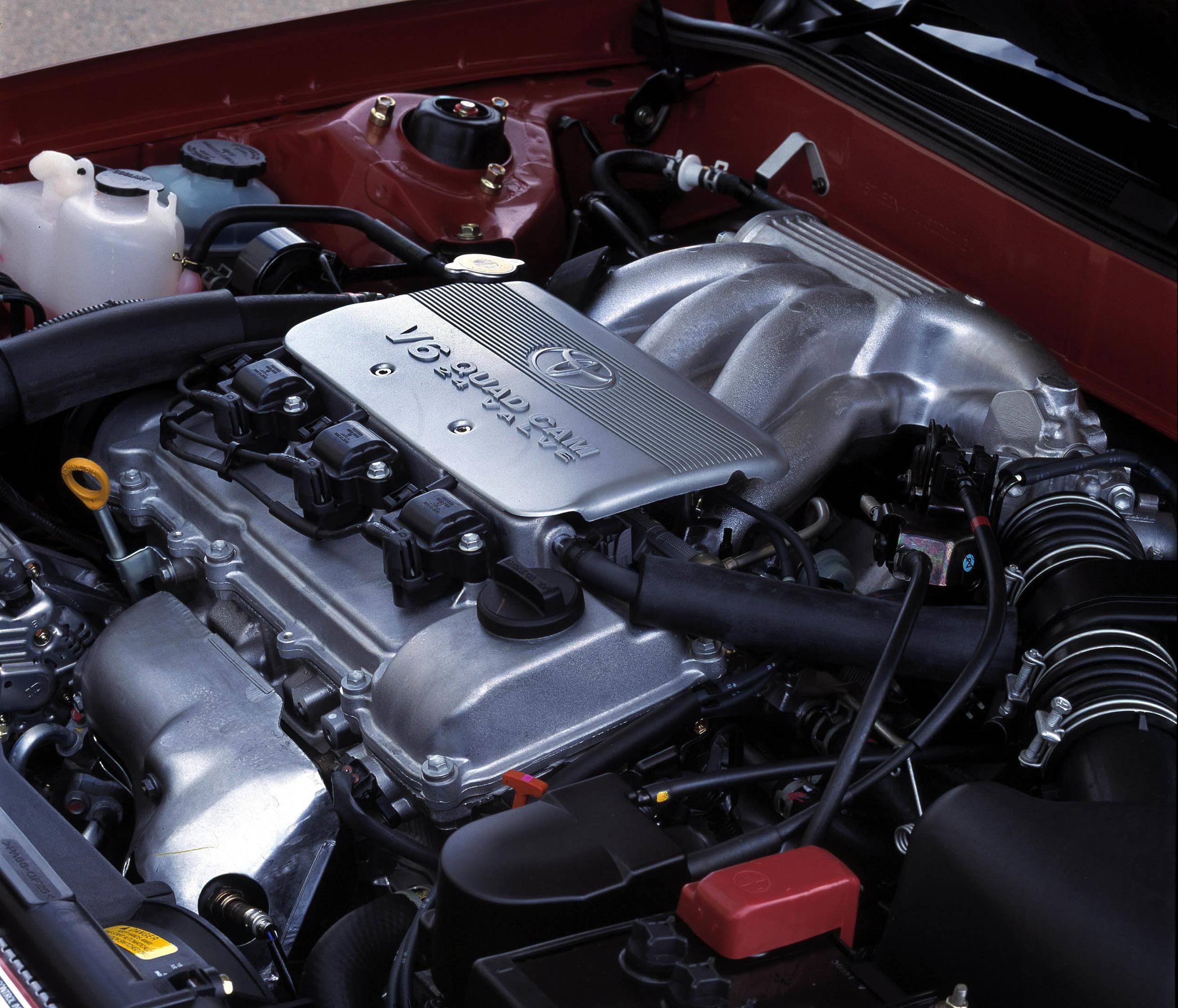
Toyota’s 3MZ-FE was a 3.3-litre V6 petrol engine with a 60-degree ‘V’ angle. A member of Toyota’s ‘MZ’ engine family, the 3MZ-FE was closely related to the 3.0-litre 1MZ-FE – its main differences relative to later versions of that engine were its 3.3-litre capacity, two-stage intake controls system and 10.8:1 compression ratio (10.5:1 for the 1MZ-FE). Unlike the 1MZ-FE, however, the 3MZ-FE was an interference engine.
For Australia, the 3MZ-FE engine was used in the Toyota XU20 Kluger, Lexus XU30 RX 330 and Lexus XU30 RX 400h.
| Years | Engine | Trans. | Peak power | Peak torque | |
|---|---|---|---|---|---|
| Toyota XU20 Kluger | 2003-07 | 3.3-litre petrol V6 | 5sp auto | 172kW at 5600rpm | 328Nm at 3600rpm |
| Lexus XU30 RX 330 | 2003-05 | 3.3-litre petrol V6 | 5sp auto | 172kW at 5600rpm | 328Nm at 3600rpm |
| Lexus XU30 RX 400h | 2006-08 | 3.3-litre petrol V6 | CVT | 155kW at 5600rpm | 288Nm at 4400rpm |
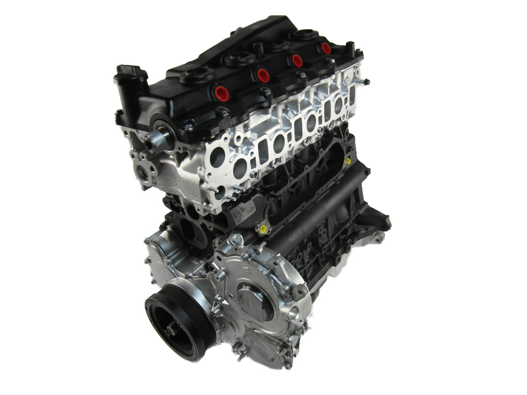
3MZ-FE block
The 3MZ-FE engine had a deep-skirt, aluminium alloy cylinder block with six bolt main bearing caps. The 3311 cc 1MZ-FE had 92.0 mm bores – with a bore pitch of 105.5 mm – and an 83.0 mm stroke. Within the bores, the 3MZ-FE had press-fitted cast-iron cylinder liners. Furthermore, the cylinder banks had an offset 36.6 mm.
The cylinder block contained a water jacket through which coolant was pumped to cool the cylinders.
Crankshaft, connecting rods and pistons
The 3MZ-FE engine had a forged steel crankshaft with four main journals, nine semi-balance weights and roll-finished pins and journals. Crankshaft bearing caps were fastened using four plastic-region tightening bolts for each journal.
Attached to the crankshaft were sintered and forged connecting rods. Like the crankshaft, the connecting rods had plastic region tightening bolts.
The 3MZ-FE engine had aluminium alloy pistons with full-floating type piston pins which had snap rings fitted on both ends of the pins; the piston skirts had a resin coating. Compared to the 1MZ-FE, the pistons for the 3MZ-FE engine were positioned slightly higher to reduce the area in which unburned fuel may accumulate during combustion.
Cylinder head and camshafts
The 3MZ-FE engine had an aluminium alloy cylinder head and a carbon graphite-type cylinder head gasket. Within the cylinder head, the 3MZ-FE engine had cast iron alloy crankshafts. The exhaust camshafts were driven by a timing belt, while the intake camshafts were driven through gears on the exhaust camshafts. The scissor gear mechanism for the exhaust camshaft was used to control backlash and suppress gear noise. The camshaft journal was supported at five places between the valve lifters on each cylinder and on the front end of the cylinder head.
Compared to the 1MZ-FE engine, the area of the combustion chamber that surrounded the valves in the cylinder head was extended to the edge of the bore – this had the effect of increasing intake and exhaust efficiency. Cooling efficiency was also improved by optimising the shape of the water passage.
Valves and VVT-i
The 3MZ-FE engine had four valves per cylinder with an included valve angle of 22.5 degrees (i.e. the angle between the intake and exhaust valves). The intake and exhaust valves were fitted with irregular pitch springs that were made of special valve spring carbon steel that was capable of following the cam profile at all engine speeds. Adjustment of valve clearance was done by means of an outer shim type system in which valve adjusting shims were located above the valve lifters – this permitted replacement of the shims without removal of the camshafts.
For the XU20 Kluger and XU30 RX 330, the ‘Variable Valve Timing – intelligence’ (VVT-i) could vary inlet camshaft timing, providing 60 degrees of valve overlap on maximum advance and no overlap on the maximum retard setting; intake and exhaust duration was 240 degrees. Inlet camshaft timing was varied according to engine speed, throttle position, accelerator pedal angle, engine coolant temperature, intake air volume and intake air temperature.
For the XU30 RX 400h, VVT-i provided 32 degrees of valve overlap on maximum advance setting and no overlap on the maximum retard setting.
| 3MZ-FE valve timing: XU20 Kluger and XU30 RX 330 | ||
|---|---|---|
| Intake | Open | -4° to 56° BTDC |
| Close | 64° to 4° ABDC | |
| Exhaust | Open | 56° BBDC |
| Close | 4° ATDC | |
The outer hub of the inlet camshaft pulley drove the exhaust camshaft via scissor gears. Inside the pulley, there was an outer gear (driven by the outer hub), a moveable oil-pressure-controlled piston and an inner gear which drove the inlet camshaft. The outer and inner gears were connected by helical splines. When the ECU required a change in inlet timing, it would send a signal to the oil control valve to provide oil pressure to either the advance or retard side of the moveable piston. The piston would then move along the helical splines, altering the drive angle of the inner gear and hence the indexing of the inlet camshaft.
Throttle control
The 3MZ-FE had a second-generation linkless electronic throttle (ETCS-i) which determined throttle angle based on accelerator position, load and engine condition. The electronic throttle provided idle speed control, shift-shock reduction control, traction control, cruise control and a snow mode.
ACIS-II and intake control system
For the 3MZ-FE engine, the intake air chamber was made of plastic and contained an intake air control valve for Toyota’s ‘Acoustic Control Induction System’ (ACIS). ACIS consisted of:
- A bulkhead to divide the intake manifold into two stages; and,
- An intake air control valve in the bulkhead which opened and closed to vary the effective length of the intake manifold according to engine speed and throttle valve opening angle.
When the engine was running at middle speed under high load, an actuator would close the intake air control valve to increase the effective length of the intake manifold and improve intake efficiency – at medium engine speeds – due to the effect of inlet pulsations. Furthermore, ACIS-II used the short-runner configuration to save fuel when the engine was idling or under light loads
In addition to ACIS, the 3MZ-FE engine had a two-stage air intake control system in which the air cleaner inlet was divided into two areas controlled by:
- A vacuum switching valve (VSV); and,
- A butterfly-type air intake control valve.
The air intake control valve closed one side of the air cleaner inlet when the engine was operating at the low-to-mid engine speeds.
Injection and ignition
The 3MZ-FE engine had sequential multi-point fuel injection – via 12 hole injectors – with a hot-wire air-flow meter to measure intake air density. The 3MZ-FE engine had Toyota’s ‘Direct Ignition System’ which consisted of six ignition coils and each coil fitted over a spark plug. The spark plug was located in the centre of the combustion chamber.
The 3MZ-FE engine had a compression ratio of 10.8:1 and a firing order of 1-2-3-4-5-6.
Exhaust
The 3MZ-FE engine had stainless steel exhaust manifolds, while the main muffler included a variable back-pressure valve. The exhaust valve opened steplessly according to back-pressure, remaining closed at low engine speeds to reduce noise and opening at higher engine speeds for improved performance.