Introduction
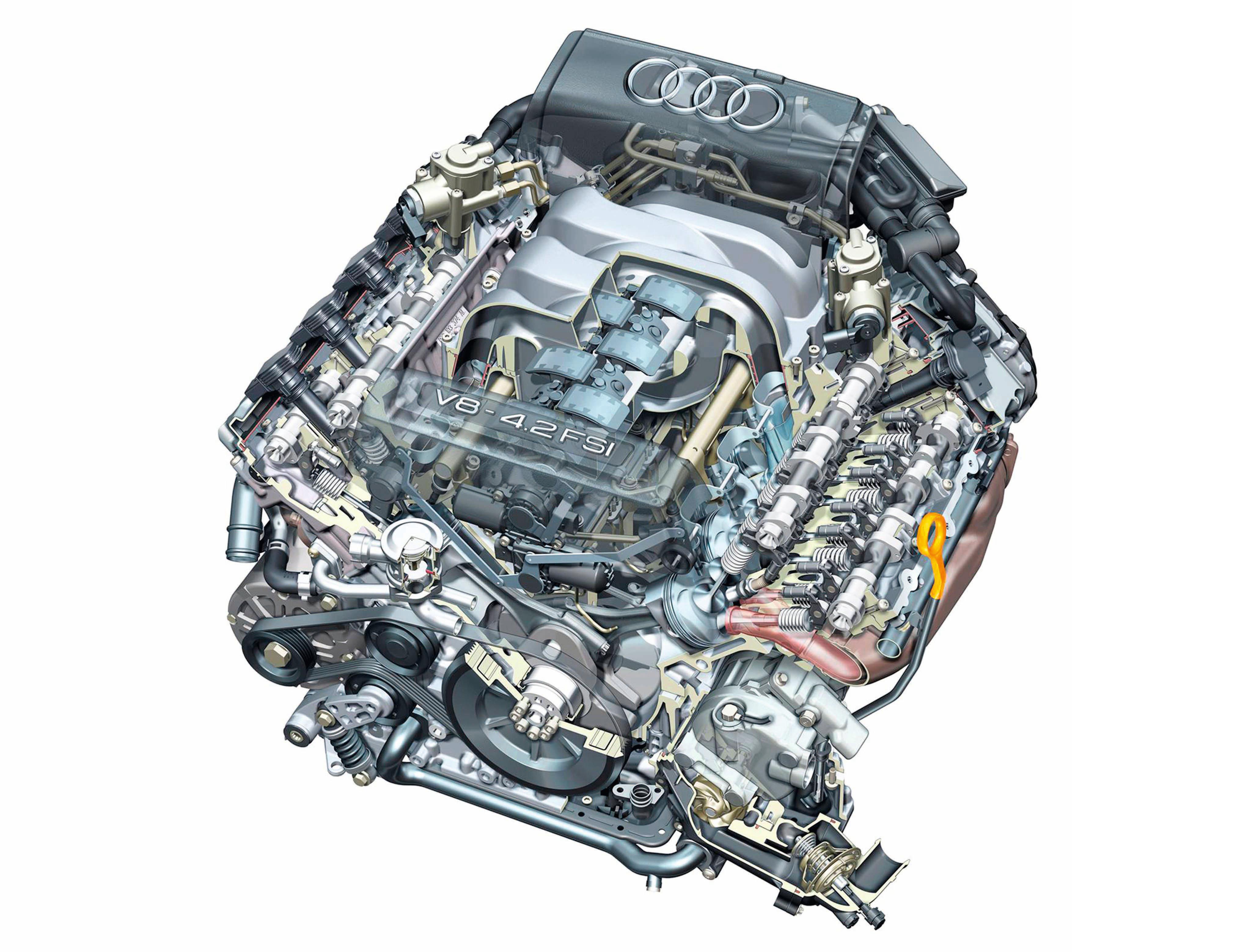
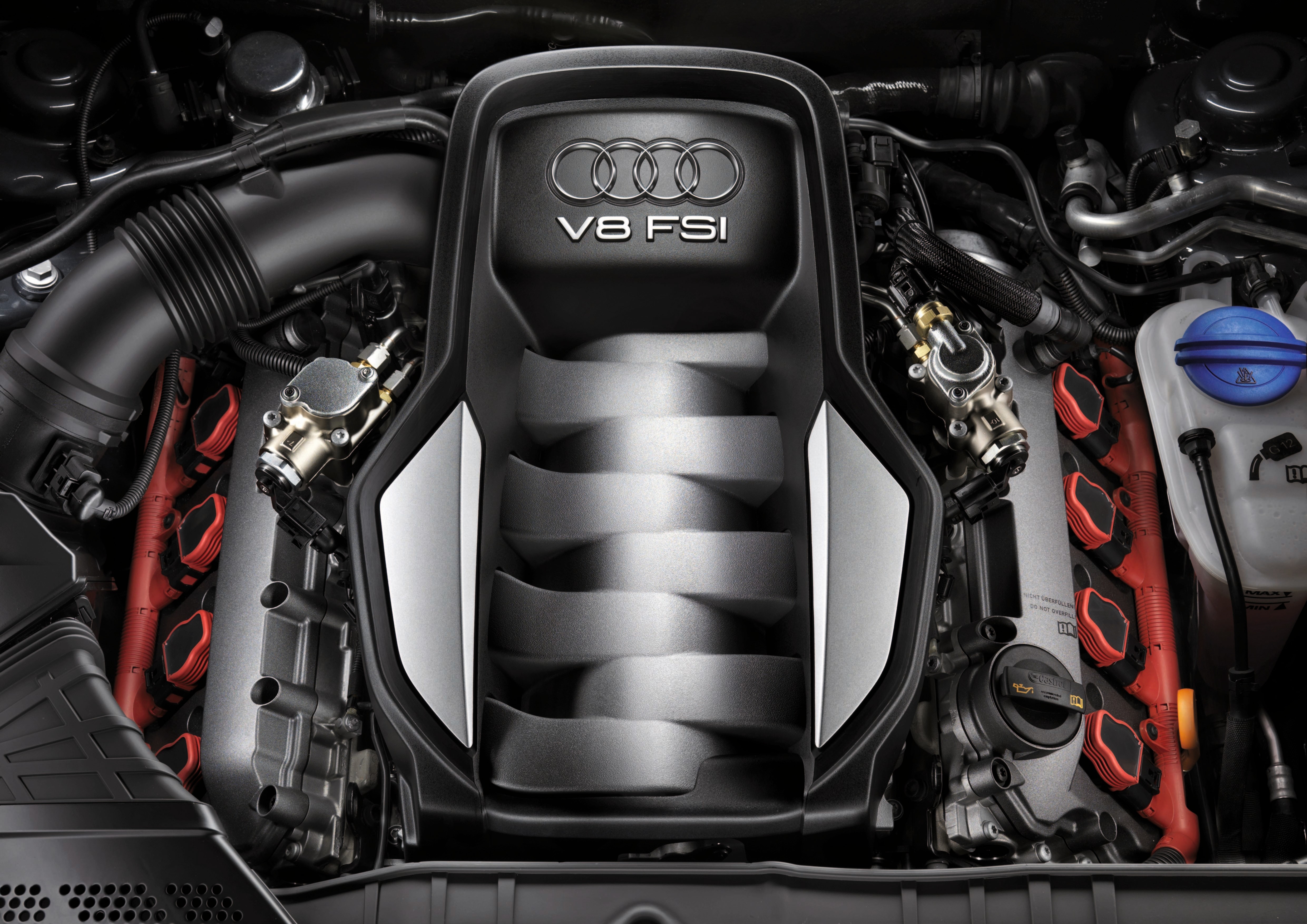
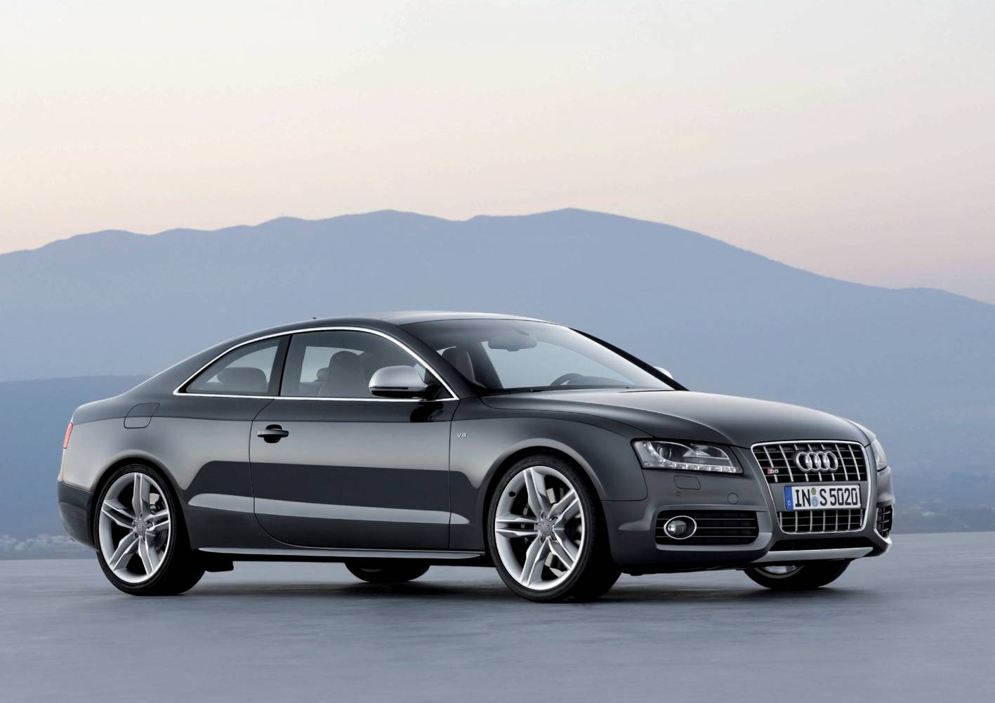
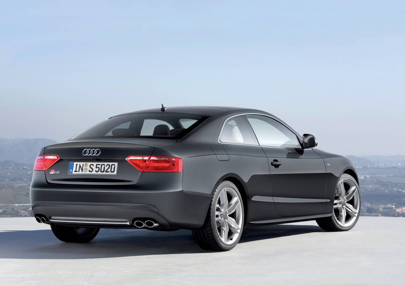
Audi’s CAUA engine was a 4.2-litre V8 petrol engine with direct injection that powered the Audi 8T S5 Coupe from 2007 to 2011. Key features of the CAUA engine included its:
- Closed-deck, aluminium silicon-alloy block with reinforcing bedplate;
- 90-degree ‘V’ angle;
- Cast aluminium alloy cylinder head;
- Double overhead camshafts (chain-driven) with inlet and exhaust camshaft timing adjustment;
- Four valves per cylinder;
- Variable intake manifold and intake manifold flap;
- Audi’s ‘Fuel Stratified Injection’ (FSI); and,
- A compression ratio of 12.5:1.
The CAUA engine produced peak outputs of 260 kW at 7000 rpm and 440 Nm at 3500 rpm. However, 85 per cent of peak torque (i.e. 352 Nm) was available from 2000 rpm.
| Model | Engine | Trans. | Peak power | Peak torque |
|---|---|---|---|---|
| Audi 8T S5 Coupe | 4.2-litre CAUA petrol V8 | 6sp man., 6sp auto |
260kW at 7000rpm | 440Nm at 3500rpm |
Block
The CAUA engine had a hypereutectic aluminium-silicon alloy (‘Alusil’, AlSi17Cu4Mg) block that was produced through low-pressure gravity die-casting and reinforced with a cast aluminium-silicon alloy bedplate. With its 84.5 mm bores – spaced at 90 mm intervals – and 92.8 mm stroke, the CAUA engine had a capacity of 4163 cc. Furthermore, the cylinder banks had an 18.5 mm offset.
To achieve narrow cylinder webs (which contained drilled cooling ducts), the CAUA engine did not have separate cylinder liners. Instead, the cylinder bores were mechanically stripped to separate the aluminium in a three-stage honing and exposure process. By stripping the aluminium from the cylinder surfaces, silicon was exposed in the form of very small and hard particles; these silicon particles were then honed under simulated mechanical stress.
The CAUA engine had five cast iron press-fit main bearing caps; each bearing cap was attached by four bolts.
Crankshaft, connecting rods and pistons
The CAUA engine had a die-forged and tempered high alloy steel (42CrMoS4) crankshaft that was supported by five bearings. From the crankshaft, the CAUA engine had 154 mm long forged trapezoidal connecting rods produced from 36MnVS4 that were cracked during the manufacturing process for precise fitment of the cap after the bearing was installed. The CAUA engine had forged aluminium pistons which weighed 290 grams each and had Ferrostan-coated skirts to prevent direct contact between the pistons and cylinder walls.
Cylinder head
The CAUA engine had an aluminium alloy cylinder head with hollow double overhead camshafts per cylinder bank. The camshafts were driven by a two-stage chain drive that was mounted on the flywheel side of the engine and used three simplex roller chains. The camshafts lobes were mated to the camshaft by a hydro-forming process during assembly and actuated the four valves per cylinder by roller finger cam followers. Furthermore, the roller finger cam followers had automatic hydraulic valve clearance adjustment.
For heat dissipation, the exhaust valve stems were filled with sodium.
Variable camshaft timing
The CAUA engine used vane adjusters for its continuously variable intake and exhaust camshaft timing. Both the intake and exhaust camshafts had an adjustment range of 42 degrees relative to crankshaft angle, while maximum valve overlap of 47 degrees.
Intake, variable intake manifold and intake manifold flaps
The CAUA engine had a fresh air intake system with two branches to reduce pressure losses. Each intake tract had a mass airflow sensor and the tracts were conjoined upstream of the throttle valve module.
The CAUA engine had a two-stage variable intake manifold that was produced from die-cast magnesium. The variable intake manifold consisted of change-over flaps that were controlled by an electric motor that, when activated, varied the length of the intake runners. At low engine speeds, long intake manifold runners were used to utilise exhaust pulsations and increase torque. At high engine speeds, however, short intake manifold runners were used to reduce intake resistance and increase power.
The intake manifold flaps were installed in the two lower intake manifold sections and controlled by an electric motor according to load and engine speed. At low loads and engine speeds, the flaps closed off the lower section of the intake ports to produce ‘cylindrically-shaped’ air flow in the cylinder. At high loads and engine speeds, the flaps sat flush against the surface of the intake ports to minimise intake resistance.
Cooling
The CAUA engine had a longitudinal cooling system whereby coolant flowed from the intake side, through the cylinder head gasket, into the cylinder head and out through the timing chain cover. At partial engine loads, coolant temperature was regulated to 105 degrees Celsius; in the full load range, however, coolant temperature was regulated to 90 degrees Celsius to suppress knocking tendencies.
Fuel Stratified Injection (FSI)
The fuel system for the CAUA engine consisted of low- and high-pressure circuits:
- For the low-pressure fuel circuit, fuel pressure of up to 7 bar (102 psi) was generated by an electric transfer fuel pump; and,
- For the high-pressure fuel circuit, fuel pressure of 25 to 105 bar (363 to 1523 psi) was generated by two mechanical high-pressure fuel pumps, each of which was driven via a dual cam by the intake camshafts.
Both high-pressure fuel pumps delivered fuel into a common line to the fuel rails, with the fuel delivery timed such that the pressure impulses of the pumps were offset at the common rail to minimise pulsations. From there, fuel was injected into the cylinders by single-hole sequential fuel injectors that were fitted on the intake side of the cylinder head and had integrated swirl plates.
Ignition
The CAUA engine had mapped direct ignition with centrally-mounted spark plugs and eight direct-acting single spark coils. The ignition process was controlled by the Bosch Motronic MED 9.1.1 engine management system which used two hot film mass airflow sensors and four knock sensors. Furthermore, the CAUA engine had a 1-5-4-8-6-3-7-2 firing order and 12.5:1 compression ratio.
Secondary air injection system
The CAUA engine had a secondary air injection system so that the catalytic converters reached their operating temperature faster. In this process, the fuel mixture was enriched to produce a higher percentage of unburnt hydrocarbons in the exhaust gas. The secondary air injection – located downstream of the exhaust valves – then enriched the exhaust gases with oxygen, causing oxidation (i.e. after-burning) of the hydrocarbons and carbon monoxide.
Crankcase breather and ventilation
The CAUA engine had a crankcase breather system to flush fresh air through the crankcase. As a result, water vapour and low-boiling hydrocarbons were removed from the crankcase and diverted back into the engine intake air to be burned. In this system, air was removed downstream of the air filter and guided into the inner ‘V’ of the cylinder block by a non-return valve. A restrictor downstream of the non-return valve then controlled the amount of fresh air supplied to the crankcase.
The CAUA engine also had a ventilation system that recycled unburnt hydrocarbons (blow-by gases) for combustion so that they did not escape into the outside air. To minimise the oil in the blow-by gases, the gases were passed through a labyrinth oil separator in the cylinder head cover and a three-stage cyclonic micro oil separator. In the cylinder head cover, the gas would pass by impact plates which separated the larger oil droplets. The gases were then channelled by hoses to the micro oil separator where smaller oil droplets were separated to prevent the accumulation of carbon deposits on the intake valves (also known as intake valve carbon build-up or coking). Despite this system, however, Volkswagen and Audi FSI engines from this period have a reputation for carbon deposits on the intake valves.