Introduction
Audi’s BNS was a 4.2-litre V8 petrol engine that was introduced in the Audi B7 RS4 in 2006. Key features of the BNS included:
- Two-piece, closed-deck cylinder block;
- 90-degree ‘V’ angle;
- Die-forged crankshaft made from 42CrMoS4;
- Split connecting rods made from 34CrNiMo8;
- Forged aluminium pistons;
- Chain-driven double overhead camshafts;
- Four valves per cylinder actuated by roller rocker arms with hydraulic lifters;
- Direct fuel injection (Audi’s ‘Fuel Stratified Injection’, or FSI);
- 4-2-1 exhaust manifold; and,
- Compression ratio of 12.5:1.
The BNS engine was 464 mm long and the cylinder block was 228 mm high.
| Model | Engine | Trans. | Peak power | Peak torque |
|---|---|---|---|---|
| Audi B7 RS4 | 4.2-litre BNS petrol V8 | 6sp man. | 309kW at 7800rpm | 430Nm at 5500rpm |
| Audi B7 RS4 Cabriolet | 4.2-litre BNS petrol V8 | 6sp man. | 309kW at 7800rpm | 430Nm at 5500rpm |
Block
The BNS engine had a two-piece, closed-deck cylinder block with 84.5 mm bores – spaced at 90 mm intervals – and a 92.8 mm stroke for a capacity of 4163 mm, while the cylinder banks had an 18.5 mm offset. The primary, upper section of the hypereutectic crankcase was made from an aluminium-silicon alloy (AlSi17Cu4Mg) in a low-pressure gravity die-cast process. To enhance its strength, it was also subject to special heat treatment.
The cylinder bores were machined in a three-stage honing and exposure process. During this process, the silicon grains in the cylinder bores (in the form of microscopic, hard particles) were stripped to provide the necessary wear resistance of the cylinder surfaces for the pistons and piston rings. Before the honing process commenced, a honing template was attached to the crankcase to simulate the warping effect of the bolted cylinder manifold. Relative to the lower-performance versions of the VW/Audi 4.2-litre FSI V8 engine, the crankcase for the BNS engine was machined to a higher specification.
The lower crankcase (bedplate bearing cross-member) was made from aluminium and had press-fitted iron main bearing covers made of grade 50 nodular cast iron. The lower crankcase was centered using centering pins, sealed with liquid sealant and then bolted to the cylinder crankcase. The bedplate had the same stabilizing effect as a ladder frame.
Crankshaft, connecting rods and pistons
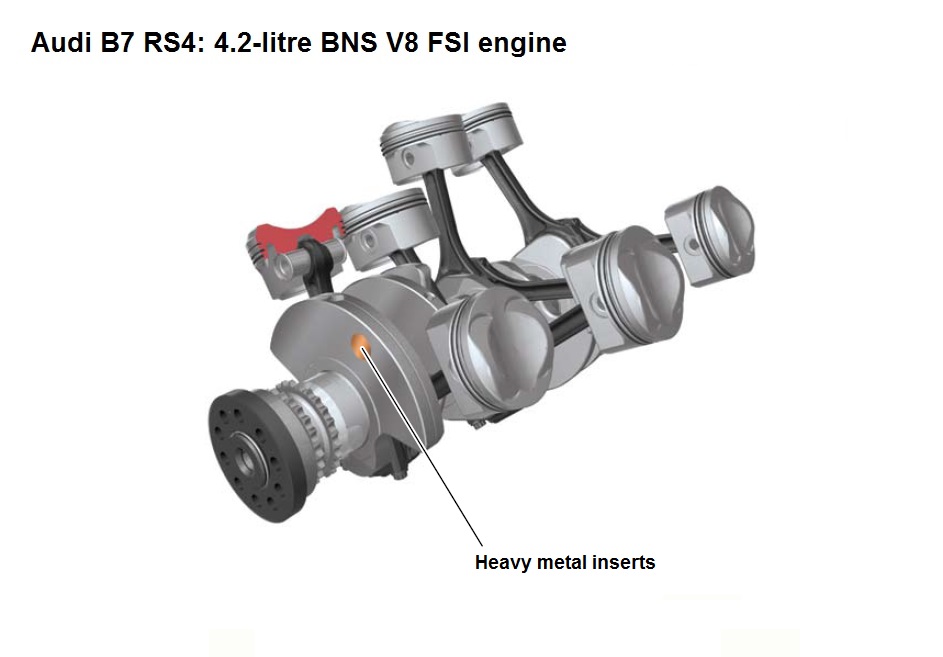
The BNS engine had a die-forged crankshaft that was made of high-alloy tempered steel (42CrMoS4) and rotated on five bearings. The main bearings were 18.5 mm wide and had a 65.0 mm diameter; the big-end bearings, however, were 15.25 mm wide and had a 54.0 mm diameter. To compensate for unwanted engine vibration, heavy metal inserts were integrated in the first and eighth crank journals by way of unbalance. Furthermore, the BNS engine had a dual-mass damper to prevent axial vibrations at high engine speeds.
The BNS engine had conventionally split connecting rods that were made of 34CrNiMo8. Relative to the lower-performance versions of the VW/Audi 4.2-litre FSI V8 engine, the geometry and tolerances for the connecting rods were reduced for the BNS engine. The connecting rods were 154 mm long, had 54 mm diameter bearing journals, and 1.4 mm thick by 15.25 mm wide bearing bushings.
The BNS engine had forged aluminium pistons that are understood to have Ferrostan-coated skirts to prevent direct contact between the pistons and the cylinder walls. The piston crowns were also adapted for direct injection to promote circular air flow in the cylinder. Without piston rings, each piston weighed 290 grams.
Cylinder head
The BNS engine had an aluminium cylinder head and double overhead camshafts with lobes that were connected through a hydroforming process. The camshafts were driven by 3/8″ simplex sleeve-type chains due to their low wear and high stress resistance properties. The four chains were arranged in two layers:
- Layer 1: chain drive A drives the camshafts’ idler gears from the crankshaft; and,
- Layer 2: top chains B and C drive the camshafts from the idler gears. Furthermore, chain drive D drove the accessory drive module from the crankshaft.
Chain tension was maintained by hydraulic tensioners; the chain drive was maintenance-free and designed for the life of the engine.
The BNS engine had four valves per cylinder that were actuated by roller finger cam followers with hydraulic backlash compensation. The intake and exhaust valves had chrome-plated stems that were filled with sodium for heat dissipation, while valve lift was 11.0 mm. Relative to lower-performance versions of the VW/Audi 4.2-litre FSI V8 engine:
- The roller cam followers had a more robust design with peened rollers;
- Stronger single valve springs were used.
For the BNS engine, the intake valve opening angle was 230 crank angle degrees and the exhaust valve opening angle was 220 crank angle degrees. Both the intake and exhaust camshafts had an adjustment range of 42 degrees, while maximum valve overlap was 47 degrees (for internal exhaust gas recirculation).
Intake system
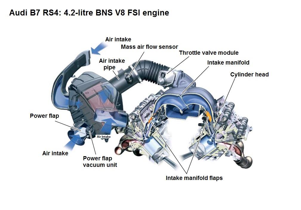
The BNS engine had a specially designed sand-cast aluminium intake manifold, with pressure loss minimised through:
- Large cross-sectional areas in the single hot-film air mass meter (HFM) and air intake pipe; and,
- A 90 mm diameter throttle valve.
Unlike lower-performance versions of the VW/Audi 4.2-litre FSI V8 engine, the BNS engine did not have a variable intake manifold.
The BNS engine had map-controlled intake manifold flaps that were activated at lower engine speeds and loads. When activated, the intake manifold flaps were brought into contact with the port baffles in the cylinder head to seal the lower part of the intake port. As a result, the air mass would flow through the upper section of the intake port and induce a tumbling, charging motion inside the cylinder. When not activated, the open intake manifold flaps would maximise the cross-sectional area of the port. The intake manifold flaps were activated by a single vacuum actuator per cylinder bank.
To prove sufficient air supply at high engine speeds, a ‘power flap’ in the air filter would open when engine speed exceeded 5000 rpm or when vehicle speed exceeded 200 km/h.
Injection and ignition
On start-up, the BNS engine used homogeneous split (HOSP) injection whereby the first, primary injection occurred approximately 300 degrees before ignition top dead centre (TDC) and a secondary injection occurred around 60 degrees before ignition TDC; ignition timing was also retarded. Since the mixture would combust relatively late and with the exhaust valves open, the catalytic converter would more quickly reach its operating temperature.
Since homogeneous split injection resulted in less complete combustion, a ‘secondary air injection’ system operated to enrich the exhaust gases with oxygen – downstream of the exhaust valves – to cause oxidation (or after-burning) of the hydrocarbons and carbon monoxide. The heat released during this process enabled the catalytic converters to reach their operating temperature within 30 seconds of start-up.
Once the catalytic converters had reached operating temperature, the engine would use homogeneous carburetion. Compared to the standard engine, the high-performance engine had higher flow injectors. Both the standard and high-performance engines, however, had compression ratios of 12.5:1 and a firing order of 1-5-4-8-6-3-7-2.
The BNS engine had two Bosch MED 9.1.1 control units that were configured in a master-slave arrangement due to the processing power required at higher engine speeds. Both control units used two hot film mass air flow sensors.
Exhaust
The BNS engine had a 4-2-1 fan-type exhaust manifold to separate the exhaust pulses until the pipes merged; the exhaust manifold was attached by a clamping flange system. To reduce exhaust emissions, the BNS engine had metal-type primary and main catalytic converters that provided less flow resistance than conventional ceramic-type converters.
The BNS engine had switchable exhaust flaps in the rear silencer. To prevent low-frequency droning noises, the flaps were closed at low engine speeds. At higher engine speeds, however, the flaps would open to reduce exhaust back pressure and flow noise. When ‘Sport’ mode was activated, the exhaust flaps would be open at idle, but close when engine speed increased to comply with noise limits.
Oil circulation
The BNS engine had a longitudinal-flow cooling system whereby coolant circulated from the outlet side to the cylinder head and then through the chain housing cover. Compared to its 40-valve V8 predecessor, cooling of the cylinder webs – which connected the cylinder chambers to the outer cylinder block wall – was improved via drilled coolant ducts with optimised cross-sectional areas.
Relative to the lower-performance versions of the VW/Audi 4.2-litre FSI V8 engine, the water jacket for the BNS engine circulated coolant to the area between the intake port and the injector to reduce temperatures in the cylinder head combustion chamber plate. Furthermore, the BNS engine had two additional coolers and two V-shaped forced-flow bores between the inlet valves because they were subjected to higher stresses. While coolant flowed continuously through one of the additional coolers, the second cooler was opened via a coolant thermostat when required.
During full throttle operation, coolant temperature was reduced to 90 degrees Celsius to suppress knocking tendencies. At part throttle, however, coolant temperature was allowed to increase to 105 degrees Celsius – the higher temperature reduced internal friction and, according to Audi, resulted in a fuel saving of approximately 1.5 per cent.
Crankcase breather and ventilation
The BNS engine used a crankcase breather to flush fresh air through the crankcase. In this process, water vapour and low-boiling hydrocarbons were removed from the crankcase and diverted back to the intake air for combustion. The air was removed downstream of the air filter and guided to the inner ‘V’ of the cylinder block by a non-return valve. A restrictor downstream of the non-return valve limited the quantity of fresh air supplied to the crankcase.
The BNS engine also had a crankcase ventilation system which captured blow-by gases for combustion. To minimise the oil contained in the blow-by gases, the gases passed through a labyrinth oil separator (in the cylinder head cover) and a three-stage cyclonic micro oil separator.


