Introduction
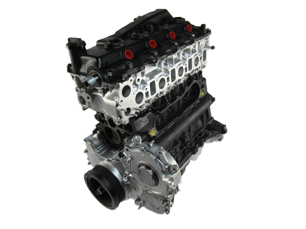
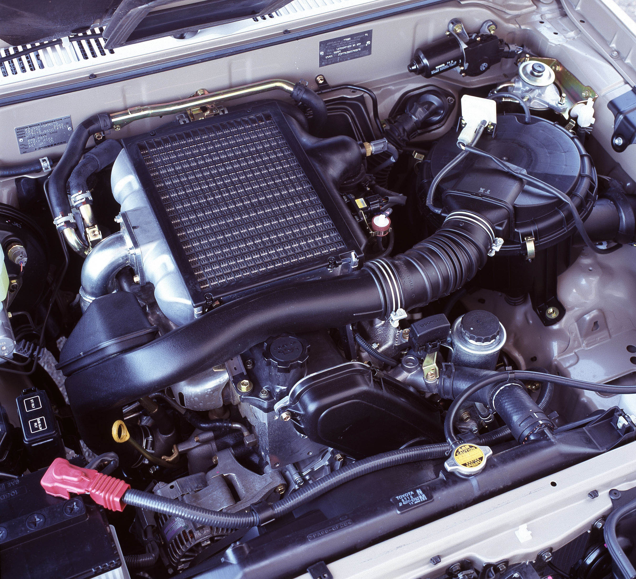
The FPV F6 270 Turbo was a turbocharged 4.0-litre inline six-cylinder petrol engine that was introduced in the FPV BA F6 Typhoon in October 2004. The FPV F6 270 Turbo was based on Ford’s BA F6 270 Turbo engine engine, but key differences included:
- A 50 per cent larger, twelve-core intercooler and dual entry ram airbox;
- 50 per cent higher maximum boost pressure of 0.64 bar (9.28 psi); and,
- Higher strength valve springs and heavy-duty connecting rods.
For the FPV BA F6 Typhoon, peak outputs for the F6 270 Turbo engine were 270 kW at 5250 rpm and 550 Nm from 2000 to 4250 rpm. However, 80 per cent of peak torque (i.e. 440 Nm) was available from 1500 rpm and 98 per cent (539 Nm) from 1750 rpm..
| Model | Engine | Trans. | Peak power | Peak torque | Years |
|---|---|---|---|---|---|
| FPV BA F6 Typhoon | 4.0-litre turbo petrol I6 | 6sp man. | 270kW at 5250rpm | 550Nm at 2000-4250rpm | 2004-05 |
| FPV BA F6 Tornado | 4.0-litre turbo petrol I6 | 6sp man. | 270kW at 5250rpm | 550Nm at 2000-4250rpm | 2005 |
| FPV BF F6 Typhoon, FPV BF F6 Tornado |
4.0-litre turbo petrol I6 | 6sp man., 6sp auto |
270kW at 5250rpm | 550Nm at 2000-4250rpm | 2005-08 |
| FPV BF Force 6 | 4.0-litre turbo petrol I6 | 6sp auto | 270kW at 5250rpm | 550Nm at 2000-4250rpm | 2006-08 |
| FPV F6X | 4.0-litre turbo petrol I6 | 6sp auto | 270kW at 5250rpm | 550Nm at 2000-4250rpm | 2008-09 |
Block
Like the BA F6 270 Turbo engine, the F6 270 Turbo engine had a cast iron block with 92.26 mm bores and a 99.31 mm stroke for a capacity of 3984 cc. Similarly, the F6 270 Turbo block had cross-bolted main bearing caps to increase rigidity and a cross-bolted alloy sump.
Cylinder head
The F6 270 Turbo engine had a gravity-cast, aluminium alloy cylinder head which was mounted on a single layer steel (SLS) sheet metal gasket. The water jacket for the F6 270 Turbo engine featured deflection vanes to squeeze coolant past hot spots – such as the exhaust valve seats – at higher velocities to achieve more even temperatures throughout the cylinder head.
Pistons and compression
Due to its forced induction, the top of the pistons for the F6 270 Turbo had a ‘dished bowl’ shape which lowered the compression ratio to 8.7:1 (compared to 9.7:1 for the naturally aspirated Barra 182). Furthermore, fully floating gudgeon pins were used to connect the piston to the connecting rod.
Dual-entry ram airbox
Unlike the BA F6 270 Turbo engine, the FPV F6 270 Turbo engine had a dual-entry ram airbox which:
- Increased airbox volume from five cubic litres to 13 litres;
- Provided more efficient airflow to the induction system; and,
- Reduced induction noise.
This dual-entry ram airbox was subsequently used in the FPV BF Boss 290 V8 engine.
Garrett turbocharger
The F6 270 Turbo engine had a Garrett GT3582R turbocharger which provided maximum boost pressure of 0.64 bar (9.28 psi). The turbocharger consisted of two elements, a turbine and a compressor, which were both installed on a single shaft. The ball bearings were supplied with engine oil from the oil supply tube which was then returned to the oil pan via the oil return pipe. The turbocharger housing received coolant from the engine cooling system.
The turbine was mounted on the exhaust manifold and used the flow of exhaust gases to drive the compressor. The compressor would then feed air to the engine’s air intake via the air-to-air intercooler which regulated the temperature of the charged air to maintain boost pressure.
The Powertrain Control Module (PCM) used a boost pressure sensor (BPS) to monitor the boost pressure of the turbocharger. Based on engine load, temperature and engine speed, boost pressure was determined by the operation of a single by-pass wastegate valve which controlled how much exhaust gas was directed to the turbine and, therefore, the turbine’s speed. In turn, the wastegate valve was operated by an actuator which had a diaphragm and used regulated air pressure.
Intake air pressure was further controlled by a blow-off valve which would dump excess pressure into the low pressure side of the intake system when the throttle was closed. The blow-off valve was actuated by intake manifold pressure, via a rubber hose from the intake manifold.
Camshafts and valvetrain
The F6 270 Turbo engine had double overhead camshafts that were driven by a single-stage roller chain. To minimise weight and improve durability at higher engine speeds, the camshafts were roll-forged and had bored centres. The four valves per cylinder were actuated by roller finger followers and a clip held the hydraulic lash adjusters to the rockers for durability. To limit in-chamber tumble and provide good seating, the valves had a domed head and no lip. It is understood that the F6 270 Turbo shared key specifications with the Barra 182 and BA F6 270 Turbo engine engines (see table below).
Variable Cam Timing (VCT)The F6 270 Turbo engine had a vane-type VCT phaser – produced by Aisin – on each camshaft that provided continual variable adjustment within a 60 degree range (10 degrees advanced or 50 degrees retarded from the initial pin lock position). Each camshaft phaser was hydraulically controlled via an oil control valve that was mounted on top of it. However, the BA F6 270 Turbo engine had Ford’s ‘Dual Equal Phase Shifting’ (DEPS) VCT system whereby the intake and exhaust camshafts could only be controlled synchronously. As such, intake and exhaust camshaft timing could only be advanced or retarded by the same degree simultaneously, and not independently. Valve timing for the initial, advanced and retarded camshaft settings are understood to be the same as the Barra 182 and BA F6 270 Turbo engine engines and are given in the tables below. Based on these timings, valve overlap was 25 degrees, intake duration was 251 degrees and exhaust duration was 246 degrees. At idle, the camshaft timing could be advanced by 10 degrees from the pin lock position for smoother running. On low throttle openings, however, the system could retard timing by as much as 50 degrees from the pin lock position to reduce fuel consumption and lower exhaust emissions via internal exhaust gas recirculation.
Dual Independent Variable Cam Timing (VCT): BF F6 270 TurboSignificantly, the variable cam timing system for the BF F6 270 Turbo engine was Ford’s ‘Dual Independent Phase Shifting’ (DIPS) which enabled the intake and exhaust camshafts to be varied independently of each other. Valve timing for the BF F6 270 Turbo engine is understood to be the same as the Barra 190 and Barra 245T engines and is given in the tables below. From these, valve overlap could be varied from -35 degrees to 85 degrees, intake duration was 256 degrees and exhaust duration was 256 degrees. Furthermore,
Injection and ignitionThe F6 270 Turbo engine had an electronically-controlled sequential fuel injection system with peak fuel delivery pressure of 4.0 bar. The ‘speed density’ fuel injection system used the engine speed, intake air temperature and manifold absolute pressure sensors to calculate intake air mass and therefore the fuel required to be injected for combustion. This quantity of fuel was then adjusted according to feedback information from the Heated Oxygen (HEGO) sensor, providing close loop control of fuel injection. The F6 270 Turbo engine had distributorless, coil-on-plug ignition with individual coils mounted above the spark plug. The long-life spark plug was positioned in the centre of the combustion chamber roof between the four valves. For the BF F6 270 Turbo engine, upgraded spark plugs were introduced which had a 0.5 mm finewire centre electrode (the smallest then available) and platinum pad ground electrodes. According to Ford, the spark plugs were optimised for idle stability and helped prevent misfire. The F6 270 Turbo engine had a 1-5-3-6-2-4 injection and firing order. For the BF F6 270 Turbo engine, the ignition system featured adaptive and variable dwell (the time required to charge the ignition coil) for more efficient ignition control. Specifically,
Internal Exhaust Gas Recirculation (EGR)The F6 270 Turbo engine complied with Euro II emission standards upon its release and had an internal exhaust gas recirculation system whereby late closing of the exhaust valves – during the downward induction stroke – would cause some of the unburned exhaust gas in the extractors to return to the intake. Knock sensing and spark correctionThe BF F6 270 Turbo engine introduced an additional knock sensor which, according to Ford, enabled a change in ignition timing strategy for more accurate spark control, improved fuel economy and greater refinement. Specifically, the Powertrain Control Module had four forms of spark control:
Back To Top
| ||||||||||||||||||||||||||||||||||||||||||||||||||||||||||||||||||||||||||||||||||||||||||


