Introduction
The Holden LF1 and LFW were 3.0-litre direct-injection V6 engines that were manufactured in Port Melbourne, Australia. Released in September 2009, the LF1 was a petrol engine that was replaced by the E85-compatible LFW engine in September 2010 (coinciding with the release of Holden’s VE.II and WM.II model ranges). Developed by GM Powertrain, the LF1 and LFW were part of General Motors’ High Feature V6 (HFV6) engine family. The 3.0-litre LF1 and LFW engines were closely related to the 3.6-litre LLT and LFX.
LF1 and LFW: block and internals
The LF1 and LFW engines both had a deep-skirt alloy cylinder block that was cast in 319 aluminium and had six-bolt main bearing caps made from copper-infiltrated sintered steel. Within the block, cast-in inter-bay breather vents reduced windage losses at high engine speeds, while the cast-iron cylinder liners were produced using a precision sand-casting process. The cylinders had a 60-degree V’ angle, 103.0 mm bore centres, 89.0 mm bores and an 80.3 mm strokes for a capacity of 2994 cc.
The LF1 and LFW engines both had a micro-alloy 1038V forged steel crankshaft (more commonly found on high performance or diesel engines), sinter-forged steel connecting rods and aluminium pistons which had polymer-coated skirts and full-floating wristpins (24 mm diameter). Furthermore, pressure-actuated piston oil-jets cooled the underside of the pistons.
LF1 and LFW: cylinder head and valvetrain
Compared to the LE0 engine, the LF1 and LFW engines had new cylinder heads that were made from A319 aluminium alloy; the new cylinder heads were necessary due to the direct injectors, higher compression ratio and high-pressure fuel pump (described further, below). Furthermore, the LF1 and LFW engines had lightweight, composite intake manifolds (previously aluminium) and integrated exhaust manifolds (replacing the previously separate high-silicon moly (SiMo) nodular cast iron exhaust manifold); the change to an integrated exhaust manifold reduced mass and provided faster catalytic converter light off.
The double overhead camshafts (per cylinder bank) were produced from cast nodular iron and had a three-chain, two-stage roller chain drive. The camshafts actuated the four valves per cylinder via roller follower valve lifters which had hydraulic lash adjusters. For the LF1 and LFW engines, both the intake and exhaust camshafts had electronically-controlled, hydraulically-actuated camshaft phasing which was continuously adjustable.
When first introduced, both the LF1 and LFW engines had twin-pipe exhaust systems. For the VF range, however, the LFW engine had a single pipe exhaust system.
LF1 and LFW: ‘SIDI’ injection and ignition
The LF1 and LFW engines had direct injection (Holden’s ‘Spark Ignition Direct Injection’, or SIDI) whereby fuel was injected directly into the combustion chamber. Since the fuel vaporised in the combustion chamber, the air/fuel mixture would cool; combined with the greater accuracy of the high-pressure injectors, the LF1 and LFW engines operated at compression ratios of 11.7:1 (compared to 10.2:1 for the LE0) for improved greater efficiency. The LF1 and LFW engines also used dual-stage injection used during cold starts to get catalytic converters up to operating temperature more quickly.
The LF1 and LFW engines both had a high pressure fuel pump that was mounted on the end of the cylinder head and driven by the exhaust camshaft. This fuel pump delivered fuel to a high strength fuel rail which then delivered fuel to a continuously variable fuel rail attached to the injectors. For the LF1 and LFW engines, fuel pump pressure was controlled between 2 MPa and 15 MPa.
The LF1 and LFW engines had E39 AC Delco electronic control units (ECUs) which featured 32-bit processing power, 2 MB of Burst Flash memory, 128 kilobytes of external RAM and 3 MB of internal SRAM.
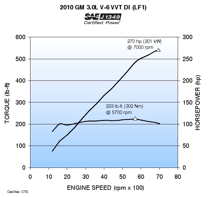
The LF1 and LFW engines had a maximum engine speed of 7000rpm and idle speed of 550 rpm.
Transmissions
The LF1 and LFW engines were initially mated to six-speed 6L50 automatic transmissions. The 6L0 transmission had three gear sets: an input planetary gear set and two output gear sets. For the 6L50 transmission, the first-to-second upshift was a free-wheeling action where the second gear clutch engaged while the first gear one-way clutch spun freely, providing greater smoothness at low engines. For gear changes from second to sixth gear, the 6L50 transmission had clutch-to-clutch’ operation whereby an oncoming’ clutch was engaged and an offgoing’ clutch released to perform gear changes.
| RPO | Engine | Peak power | Peak torque | Models | Years |
|---|---|---|---|---|---|
| LF1 | 3.6-litre petrol V6 | 190kW at 6700rpm | 290Nm at 2900rpm | VE.I Commodore, VE.I Berlina, VE.I Sportwagon |
2009-10 |
| VE.I Ute | 2010 | ||||
| LFW | 3.0-litre petrol/E85 V6 | 190kW at 6700rpm | 290Nm at 2900rpm | VE.II Commodore, VE.II Berlina, VE.II Sportwagon, VE.II Ute |
2010-13 |
| VF Commodore, VF Sportwagon |
2013-17 |