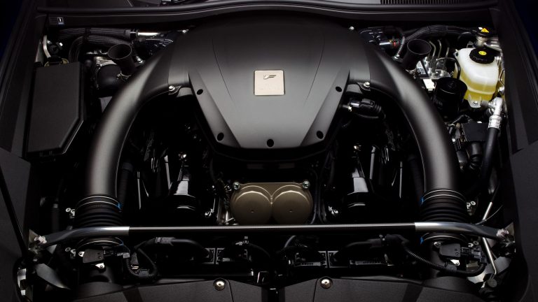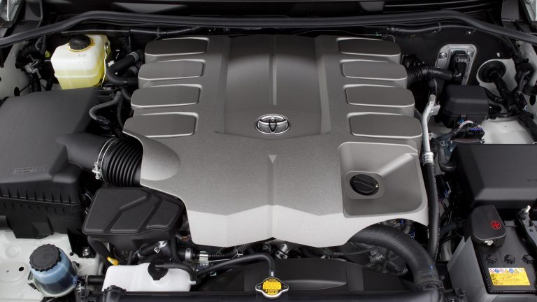
[su_image_carousel source=”media: 52137,52138″]
Introduction
Toyota’s 1UR-FE was a 4.6-litre V8 petrol engine with a 90-degree ‘V’ angle. A member of Toyota’s ‘UR’ engine family, the 1UR-FE replaced the 2UZ-FE engine but – unlike the closely related 1UR-FSE engine – did not have direct injection. Key features of the 1UR-FE engine included its aluminium alloy block and cylinder head, double overhead camshafts (chain-driven), four valves per cylinder, and variable intake and exhaust camshaft timing (‘Dual VVT-i’).
The 1UR-FE engine had a service weight of 216.1 kg.
[su_table responsive=”yes”]
| Engine | Trans. | Years | Peak power | Peak torque | |
|---|---|---|---|---|---|
| Toyota200-Series LandCruiser | 4.6-litre petrol V8 | 6sp auto | 2012-on | 228kW at 5500rpm | 439Nm at 3500rpm |
[/su_table]
1UR-FE block
The 4608 cc 1UR-FE engine had a die-cast aluminium alloy block with 94.0 mm bores and an 83.0 mm stroke; bore pitch was 105.5 mm, while the cylinder banks had a 21.0 mm offset. Within the bores, the 1UR-FE engine had spiny-type cast iron liners that were manufactured so that their casting exteriors formed large, irregular surfaces for better adhesion between the liners and the block – this improved heat dissipation and reduced heat deformation of the bores.
The 1UR-FE engine had a coolant pathway between the left and right cylinder banks that enabled water to flow between the cylinder banks, to the cylinder head and the water jackets of each cylinder bank. To keep the cylinder walls at a uniform temperature, the water jackets had plastic spacers that controlled coolant flow.
Air passage holes on the bulkheads of the cylinder block improved airflow at the bottom of the cylinders, thereby reducing back pressure generated by the reciprocal movement of the pistons and reducing pumping losses.
Crankshaft, connecting rods and pistons
The 1UR-FE engine had a forged steel crankshaft with six balance weights and five main bearing journals. The crankshaft bearings were made of aluminium alloy, while the bearing lining surface was coated with resin to improve wear and seizure resistance. The crankshaft bearing caps had four plastic region tightening bolts of different sizes in the inner and outer sides to secure the journals; each crankshaft bearing cap was tightened laterally to improve reliability. To reduce noise and vibration, the crankshaft pulley had a torsional rubber damper.
The 1UR-FE engine had forged connecting rods with resin-coated aluminium bearings. To minimise the shifting of the bearing caps during assembly, knock pins were used at the mating surfaces of the bearing caps. Furthermore, the connecting rods had plastic region tightening bolts.
The 1UR-FE engine had aluminium alloy pistons that were cooled by four oil jets in the cylinder block. To reduce friction and improve wear resistance, the piston skirts had a resin coating, while the no.1 compression ring and oil ring had a Physical Vapor Deposition (PVD) coating. To reduce weight, the bottom of the piston head (near the pin bosses) had cast holes. Furthermore, the piston head for the 1UR-FE engine had a taper squish shape.
Cylinder head
The 1UR-FE had an aluminium alloy cylinder head that separated the cam journal portion (camshaft housing) from the cylinder head. The cylinder head was mounted on a three-layer steel-laminate type cylinder head gasket, while a shim was used around the cylinder bore of each gasket to enhance sealing and durability. Furthermore, the surface of the gasket was coated with heat-resistant fluoro rubber.
The 1UR-FE had aluminium cylinder head covers which included an oil delivery pipe for lubrication of the sliding parts of the valve rocker arms. Furthermore, fresh air was drawn from the right and left bank cylinder head covers to improve ventilation inside the engine and improve the deterioration resistance of the engine oil.
Oil separator
The 1UR-FE engine had a plastic separator case that was positioned between the cylinder block and the intake manifold to separate the engine oil in the blowby gas. Oil was separated from blowby gases through an ‘inertial impaction’ system whereby blowby gases would come into contact with a baffle plate, adhere and accumulate on the plate and then drip downwards.
Camshafts and timing chains
The 1UR-FE engine had double overhead camshafts per cylinder bank that were made from cast iron alloy. The 1UR-FE used separate, primary timing chains for the intake camshafts, while each exhaust camshaft was driven by a secondary timing chain from the intake camshaft.
Both the primary and secondary timing chains were roller-type chains with a pitch of 9.525 mm. Each primary timing chain and secondary timing chain had a chain tensioner that used oil pressure and a spring to maintain chain tension. A chain oil jet in the oil pump cover was used to lubricate the timing chains.
The timing chain cover had an integrated construction which consisted of a cooling system (i.e. a water pump and water passage) and a lubrication system (oil pump and oil passage).
Valves
The 1UR-FE engine had four valves per cylinder – two intake and two exhaust – that were actuated by roller rocker arms with built-in needle bearings, the latter reducing friction between the cams and the valve rocker arms.
Located at the fulcrum of the roller rocker arms, the 1UR-FE engine had a hydraulic lash adjuster which consisted of a plunger, a plunger spring, a check ball and a check ball spring. The hydraulic lash adjuster was actuated by engine oil supplied from the cylinder head and an integrated spring. The oil pressure and the spring force that acted on the plunger pushed the roller rocker against the cam to adjust the clearance between the valve stem and rocker arm.
Dual Variable Valve Timing – intelligent (Dual VVT-i)
The 1UR-FE engine had Toyota’s ‘Dual VVT-i’ to control the intake and exhaust camshafts within a range of 40 degrees and 32 degrees of crankshaft angle, respectively. As per the table below, valve overlap for the 1UR-FE engine ranged from -26 degrees to 46 degrees (a range of 72 degrees); intake duration was 232 degrees and exhaust duration was 234 degrees.
[su_table responsive=”yes”]
| 1UR-FE Dual VVT-i valve timing | ||
|---|---|---|
| Intake | Open | -18° to 22° BTDC |
| Close | 70° to30° ABDC | |
| Exhaust | Open | 62° to 30° BBDC |
| Close | -8° to 24° ATDC | |
[/su_table]The 1UR-FE engine had VVT-i controllers on the front of the intake and exhaust camshafts that consisted of an outer housing that was driven by the timing chain sprocket and a vane coupled to each camshaft. The intake side used a VVT-i controller with three vanes and the exhaust side used one with four vanes.
By using engine speed, intake air mass, throttle position and engine coolant temperature, the ECM calculated optimal valve timing for each driving condition and controlled the camshaft timing oil control valves. In response to signals from the ECM, the camshaft timing oil control valve controlled the spool valve which allowed hydraulic pressure to be applied to the advance or retard side of the VVT-i controller. In response, rotation of the VVT-i controller vane sub-assembly – relative to the timing chain sprocket – varied valve timing. Furthermore, the ECM used signals from the intake and exhaust VVT sensors for each bank and the crankshaft position sensor to detect actual valve timing, thus providing feedback control to achieve target valve timing.
When the engine stopped, the intake side VVT-i controller was locked at the most retarded angle by its lock pin and the exhaust side controller was locked at the most advanced angle for easier starting.
Intake and throttle
For the 1UR-FE engine, the intake air chamber was made of plastic and contained an intake air control valve for Toyota’s ‘Acoustic Control Induction System’ (ACIS). ACIS consisted of:
- A bulkhead to divide the intake manifold into two stages; and,
- An intake air control valve in the bulkhead which opened and closed to vary the effective length of the intake manifold according to engine speed and throttle valve opening angle.
When the engine was running at middle speed under high load, an actuator would close the intake air control valve to increase the effective length of the intake manifold and improve intake efficiency – at medium engine speeds – due to the effect of inlet pulsations. In any condition other than middle speed running under high loads, the intake air control valve was open to shorten the effective length of the intake manifold.
In contrast to a conventional throttle which used accelerator pedal effort to determine throttle angle, Toyota’s ‘Electronic Throttle Control System – intelligent’ (ETCS-i) used the ECM to calculate the optimal throttle valve angle and a throttle control motor to control the angle. The 1UR-FE engine had a linkless-type throttle body that integrated the throttle position sensor and throttle control motor. Furthermore, ETCS-i controlled the Idle Speed Control (ISC), Active Traction Control (TRAC), Vehicle Stability Control (VSC) and cruise control functions.
The 1UR-FE engine had Siamese type intake ports whereby port diameter gradually decreased towards the combustion chamber to optimise air flow.
Injection and Ignition
The 1UR-FE engine had stamped steel fuel delivery pipes that connected to the twelve-hole fuel injectors. The L-type sequential fuel injection (SFI) used a hot-wire, slot-in type air flow meter to measure intake mass – this meter allowed a portion of intake air to flow through the detection area so that the air mass and flow rate could be measured directly. The mass air flow meter also had a built-in intake air temperature sensor.
The 1UR-FE engine had an independent injection system in which fuel was injected once into each intake port for each two revolutions of the crankshaft. Fuel injection took two forms:
- Synchronous injection which always occurred at the same timing relative to the firing order. Synchronous injection could be further divided into group injection (conducted during a cold start) and independent injection (conducted after the engine had started); and,
- Non-synchronous injection in which injection occurred regardless of the crankshaft angle.
The 1UR-FE engine had pentroof-type combustion chambers with a taper squish shape.
The 1UR-FE engine had Toyota’s independent ‘Direct Ignition System’ (DIS) ignition system which used one ignition coil (with integrated igniter) for each cylinder. Ignition timing was determined by the ECM based on signals from sensors and adjusted in response to engine knocking.
The 1UR-FE engine had long-reach, iridium-tipped spark plugs – poisoned in the centre of the combustion chamber – so that the surrounding cylinder head could be made thicker and the water jacket near the combustion chamber extended. The iridium-tipped spark plugs had 200,000 service internals and, according to Toyota, provided greater performance and durability than platinum-tipped spark plugs.
The 1UR-FE engine had a compression ratio of 10.2:1 and firing order of 1-8-7-3-6-5-4-2.
Exhaust and emissions
The 1UR-FE engine had stainless steel exhaust manifolds and the exhaust manifold for each bank used a single structure with a four-into-one grouping. For rigidity and heat dissipation, the exhaust manifold heat insulator was made of corrugated aluminium.
The 1UR-FE engine had stainless steel exhaust pipes; the front exhaust pipe had two ceramic three-way catalytic converters on both the left and right exhaust pipe banks.
To reduce emissions, the 1UR-FE engine had:
- Exhaust Gas Recirculation EGR): a step motor was used on the EGR valve so that the ECM could directly control the EGR valve and water circulated through the EGR valve for cooling;
- An air injection system – which consisted of air pump, an air switching valve and an air pressure sensor for each cylinder bank – for faster warm-up of the three-way catalytic converters (TWC); and,
- An evaporative emission control system that prevented fuel vapours created in the fuel tank from being released into the atmosphere by catching them in an activated charcoal canister.