[su_image_carousel source=”media: 52192,52193,52194,52195,52196″]
Introduction
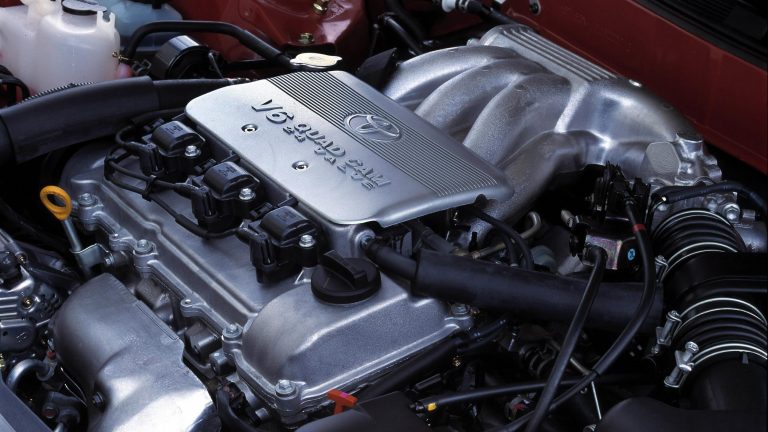
The Toyota 2GR-FKS engine was a 3.5-litre V6 petrol engine which was first introduced in 2015 for the Lexus L10.II GS 350 and Lexus AL20 RX 350. Subsequently, however, the 2GR-FKS engine powered the 2016 Toyota Tacoma and the Toyota XU50.II Kluger (sold in the USA as the Highlander).
An evolution of the 2GR-FSE, the 2GR-FKS engine introduced the following changes:
- Atkinson cycle operation (as previously used in the 2UR-GSE and 8AR-FTS engines);
- The intake camshafts were equipped with VVT-iW;
- The exhaust manifold was integrated into the cylinder head; and,
- Cooled exhaust gas recirculation.
As such, the 2GR-FKS was the first Toyota/Lexus engine to combine VVT-iW and D-4S.
[su_table responsive=”yes”]
| Engine | Trans. | Years | Peak power | Peak torque | |
|---|---|---|---|---|---|
| Lexus L10.II GS 350 | 3.5-litre 2GR-FKS petrol V6 | 8sp auto | 2015-on | 232 kW at 6400 rpm | 380 Nm at 4800 rpm |
| Lexus AL20 RX 350 | 3.5-litre 2GR-FKS petrol V6 | 8sp auto | 2015-on | 221 kW at 6300 rpm | 370 Nm at 4700 rpm |
| 2016 Toyota Tacoma | 3.5-litre 2GR-FKS petrol V6 | 8sp auto | 2015-on | 207 kW at 6000 rpm | 359 Nm at 4600 rpm |
| Toyota XU50.II Kluger/ Highlander | 3.5-litre 2GR-FKS petrol V6 | 8sp auto | 2016-on | 207 kW (est.) | 359 Nm (est.) |
[/su_table]
2GR-FKS block
With its die-cast aluminium alloy cylinder block, the cylinder banks of the 2GR-FKS engine had a 60-degree ‘V’ angle. The 2GR-FKS engine had 94.0 mm bores and an 83.0 mm stroke for a capacity of 3456 cc; bore pitch was 105.5 (i.e. the distance between the centre of adjacent bores), while cylinder bank offset was 36.6 mm.
Like the related 2GR-FE engine, the 2GR-FKS engine had ‘spiny type’ cast-iron cylinder liners – the casting exteriors of these liners have irregular surfaces to enhance the adhesion between the liners and the aluminium cylinder block.
Crankshaft, connecting rods and pistons
The 2GR-FKS’s forged steel crankshaft had four main bearing journals and five balance weights. The crankshaft bearings were made of aluminium alloy, while the bearing lining surface had a resin coating to reduce wear and resist seizure; around their inside circumference, the upper crankshaft bearings also had an oil groove. The crankshaft bearing caps were tightened using four (4) plastic region tightening bolts for each journal.
The 2GR-FKS engine had forged connecting rods which used aluminium bearings. To reduce mass, the connecting rods and caps were made of high-strength steel and nutless-type plastic region tightening bolts. Furthermore, knock pins were used at the mating surfaces of the bearing caps to minimise movement during assembly.
The 2GR-FKS had aluminium alloy pistons with a resin coating to reduce friction. The top of the pistons had a ‘taper squish’ shape to improve mixture formation, while the groove of the top ring was coated with alumite for abrasion resistance. Oil jets for cooling and lubricating the pistons were located in the cylinder block sum-assembly (in the centre of the right and left banks); these jets contained a check valve to prevent oil from being fed when oil pressure was low.
Cylinder head
The 2GR-FKS had an aluminium alloy cylinder head with a two-piece structure in which the head was divided at the cam journals. Like the 2GR-FE, the 2GR-FKS engine had a steel-laminate type head gasket; a shim was used around the cylinder bore of each gasket to improve sealing and durability.
Camshafts and roller rockers
The 2GR-FKS engine had double overhead camshafts that were made of cast iron alloy. Both the primary and secondary timing chains used pitch roller chains with a pitch of 9.525 mm. The intake camshafts were driven by the crankshaft via the primary timing chain. The exhaust camshafts were driven by the intake camshaft of the respective bank via the secondary timing chain.
The primary timing chain used one chain tensioner (ratchet type with a non-return mechanism), and each of the secondary timing chains for the right and left banks used one chain tensioner. Both the primary and secondary chain tensioners used a spring and oil pressure to maintain proper chain tension at all times. Furthermore, the timing chains were lubricated by oil jets.
The timing chain cover incorporated the cooling system (water pump and passage) and the lubrication system (oil pump and oil passage), with the latter connected to an oil control solenoid assembly for VVT-iW control.
The 2GR-FKS engine had roller rocker arms with built-in needle bearings that reduced the friction that occurred between the camshafts and the roller rocker arms (which actuated the valves). The hydraulic lash adjuster – located at the fulcrum of the roller rocker arm – consisted primarily of a plunger, plunger spring, check ball and check ball spring. Through the use of oil pressure and spring force, the lash adjuster maintained a constant zero valve clearance.
Valves
Like the 2GR-FE, the 2GR-FSE engine had four valves per cylinder (two intake and two exhaust) with the following properties –
- Intake valves: 38.0 mm diameters and 10.9 mm valve lift; and,
- Exhaust valves: 32.0 mm diameters and 10.7 mm valve lift.
Variable Valve Timing – Intelligent Wide (VVT-iW)
While the exhaust camshaft for the 2GR-FKS engine enabled variable exhaust valve timing (VVT-i), the intake camshaft had a mid-position camshaft lock mechanism which could retard intake valve timing – known as ‘Variable Valve Timing – Intelligent Wide’ (VVT-iW) – which enabled the 2GR-FKS engine to:
- Start in the Otto cycle;
- Switch to an Atkinson cycle (i.e. shortened compression stroke and longer expansion stroke) for low-rev operations to minimise fuel consumption; and,
- Use an Otto cycle at higher engine speeds for greater power.
For variable valve timing, the 2GR-FKS engine adopted ‘centre-spool’ type control with the oil-control valve integrated in the variable valve timing (VVT) system to shorten the oil path for greater responsiveness and reliability in cold conditions. Furthermore, Magnetic Resistance Element (MRE) type VVT sensors were used.
For the 2016 Toyota Tacoma, valve timing is given in the table below.
[su_table responsive=”yes”]
| 2GR-FKS Valve Timing | ||
|---|---|---|
| Intake | Open | -33° to 47° BTDC |
| Close | 105° to 25° ABDC | |
| Exhaust | Open | 64° to 14° BBDC |
| Close | 0° to 46.5° ATDC | |
[/su_table]
Otto and Atkinson cycles
In a conventional (Otto) cycle engine, compression stroke volume and expansion stroke volume are practically identical, such that the compression ratio and expansion ratio are also identical. Hence, any attempt to increase the expansion ratio also increases the compression ratio, and hence the likelihood of engine knock or pre-ignition. Please note that:
- Expansion ratio = (expansion stroke volume + combustion chamber volume)/combustion chamber volume; and,
- Compression ratio = (compression stroke volume + combustion chamber volume)/combustion chamber volume.
Toyota described the 2GR-FKS engine as having an ‘Atkinson cycle’ since the compression stroke was shortened and the expansion stroke extended. This was achieved by keeping the intake valves open during the initial stage of the compression stroke (when the piston was ascending) to allow a reverse flow of intake air into the intake manifold – this allowed for an increase in throttle valve opening in part load conditions, thereby reducing intake manifold vacuum and pumping losses. Furthermore, closure of the intake valves was delayed until the end of the expansion stroke, thereby increasing the expansion ratio.
Since this ‘Atkinson’ operation used a smaller portion of the compression stroke to compress the intake air, it did not take in as much air as a comparable Otto cycle engine and had lower power density, yet higher thermal efficiency.
D-4S (Direct injection 4-stroke gasoline engine Superior)
The 2GR-FKS engine had a ‘D-4S’ (Direct injection 4-stroke gasoline engine Superior) injection system which combined direct injection and conventional port injection, and required separate low- and high-pressure fuel systems. While the low pressure fuel pump controlled fuel pressure in a range between 300 and 530 kPa for port injection, the high pressure fuel pump provided pressure in the range of 2 to 20 MPa for direct injection. The 2GR-FKS engine had 12-hole, long nozzle type injectors for port injection; slit-nozzle type injectors which had a single orifice were used for direct injection.
On start-up, the 2GR-FKS adopted a ‘weak stratified-charge’ strategy whereby the port injector would inject fuel during the expansion and intake strokes before the intake valves opened. Homogeneous charge was introduced when the intake valves opened. During the latter part of the compression stroke, the direct-injector spurted fuel into the cavity in the piston crown, forming ‘weak lean stratified charge’; in the combustion chamber, the air/fuel ratio was around 15:1. The centrally positioned spark plug would ignite the richer mixture during the expansion stroke. This combustion process would retard ignition timing without adverse effects in the engine’s running, enabling higher exhaust temperature to quickly light off the catalyst. Since the cavity in the top of the piston was solely for this weak stratified-charge operation, the cavity itself was only 5.0 mm deep.
At medium or high loads at lower engine speeds, both the direct and port injection systems were used and the injection ratio was continuously varied to create a homogeneous air-fuel mixture to stabilise combustion, improve fuel efficiency and reduce emissions.
When the engine was running under heavy load, direct injection was used – this provided an intake cooling effect by injecting fuel directly to the combustion chamber which improved the efficiency of each charge and enabled the engine to operate at a compression ratio of 11.8:1.
Intake, ACIS and ETCS-i
For the 2GR-FKS engine, the intake air chamber was made of plastic and contained an intake air control valve for the Toyota/Lexus ‘Acoustic Control Induction System’ (ACIS). ACIS consisted of:
- A bulkhead to divide the intake manifold into two stages; and,
- An intake air control valve in the bulkhead which opened and closed to vary the effective length of the intake manifold according to engine speed and throttle valve opening angle.
When the engine was running at middle speed under high load, an actuator would close the intake air control valve to increase the effective length of the intake manifold and improve intake efficiency – at medium engine speeds – due to the effect of inlet pulsations. In any condition other than middle speed running under high loads, the intake air control valve was open to shorten the effective length of the intake manifold.
The 2GR-FKS engine had a linkless-type throttle body in which the throttle position sensor and the throttle control motor were integrated. Furthermore, the ‘Electronic Throttle Control System – intelligent’ (ETCS-i) controlled the throttle valve in accordance with the amount of accelerator pedal effort and the condition of the engine
The 2GR-FKS had a thin-wall cast aluminium inlet manifold and Siamese-type intake ports whereby the intake port diameter gradually decreased toward the combustion chamber to optimise airflow speed and intake pulsation.
Ignition
The 2GR-FKS engine had a coil-on-plug ignition system, the Toyota/Lexus ‘Direct Ignition System’ (DIS), in which the spark plug cap was integrated with the ignition coil. Positioned in the centre of the combustion chamber, the 2GR-FKS engine used long-reach iridium-tipped spark plugs so that:
- The top of the combustion chamber could be thicker than normal; and,
- The water jacket could be extended near the combustion chamber for better cooling.
Ignition timing was determined by the ECU based on signals from various sensors; the ECU corrected ignition timing in response to engine knocking.
The 2GR-FKS engine had ‘slanted squish’ combustion chambers; the firing order was 1-2-3-4-5-6.
Exhaust and emissions
For the 2GR-FKS engine, the stainless-steel exhaust manifold was integrated into the cylinder head, had a dual-pipe (air gap) structure and a built-in three-way catalytic converter. For emissions reduction, the 2GR-FKS engine had a cooled exhaust gas recirculation (EGR) circuit.


