Introduction
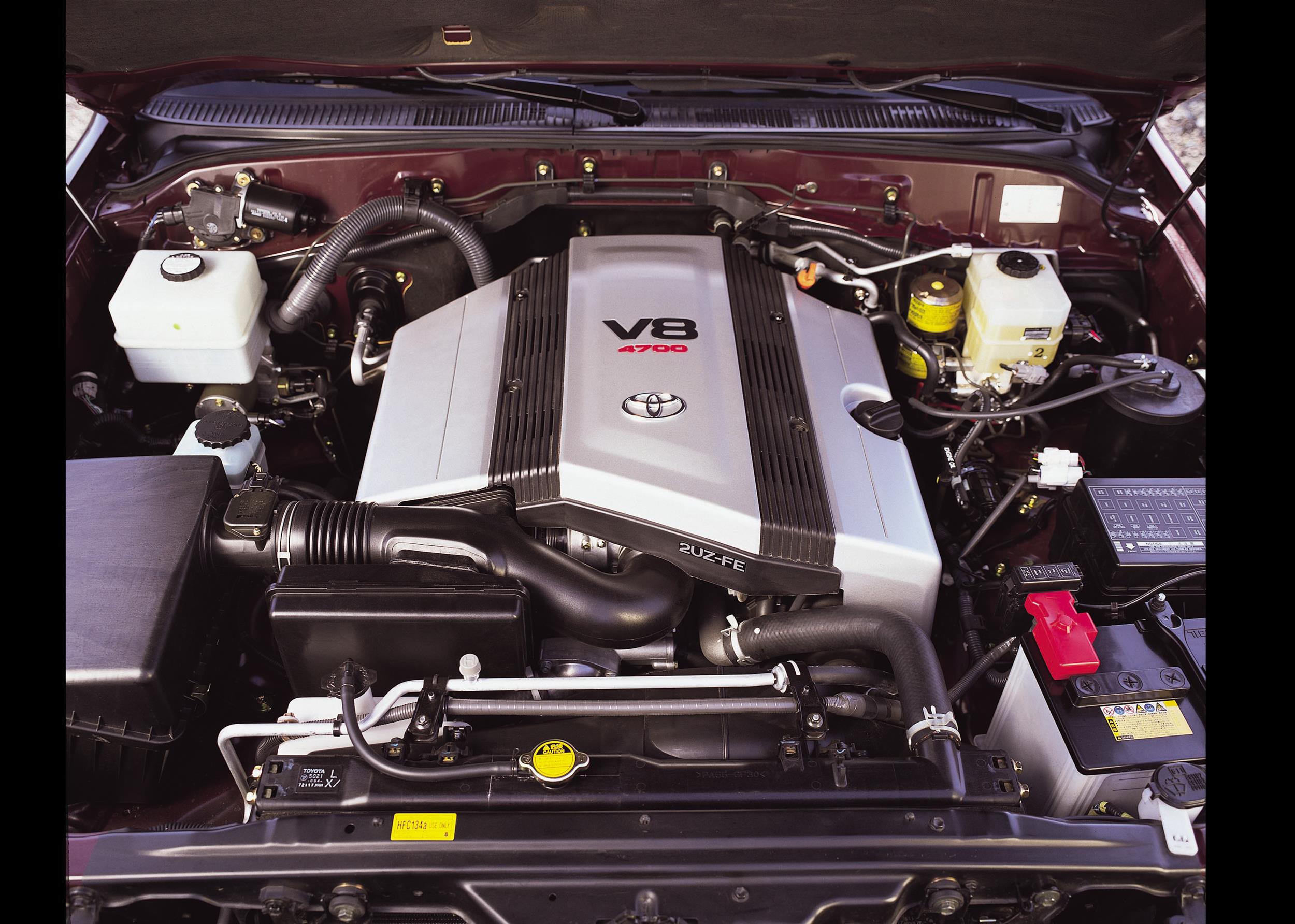
Toyota’s 2UZ-FE was a 4.7-litre V8 petrol engine which had a 90 degree ‘V’ angle and was developed for low-rev, high-torque applications. Unlike the other members of Toyota’s UZ engine family, i.e. the 1UZ-FE and 3UZ-FE, the 2UZ-FE had a cast iron block – this contributed to the 2UZ-FE’s high service mass of 255.5 kg.
In Australia, the 2UZ-FE engine was first introduced in the 100-Series LandCruiser and produced peak outputs of 170 kW at 4800 rpm and 410 Nm at 3400 rpm; 82 per cent of peak torque (340 Nm), however, was available from 1200 rpm.
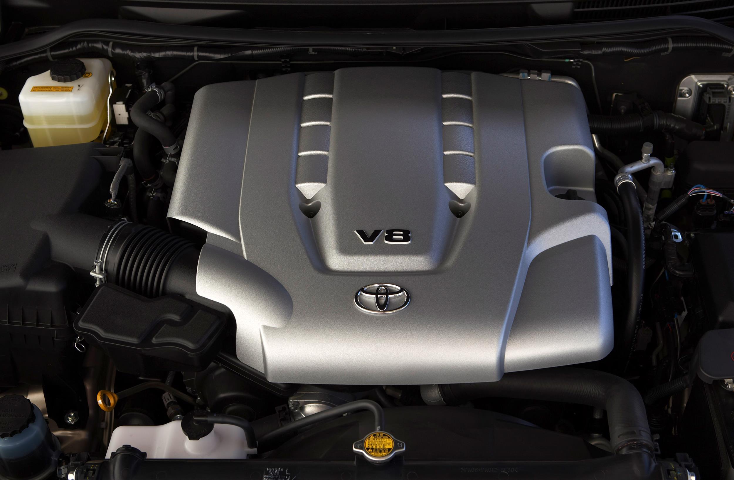
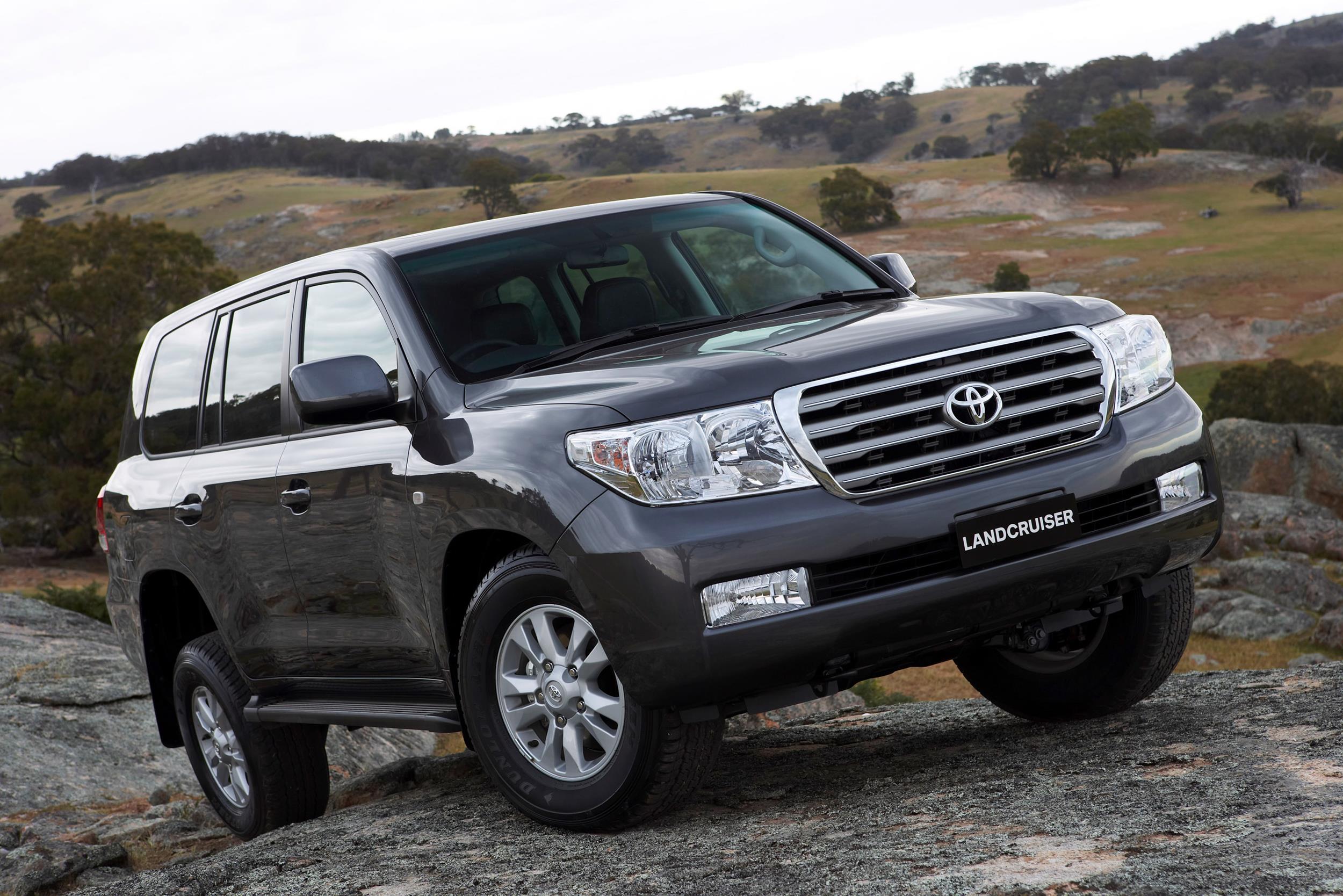
For the 200-Series LandCruiser, the 2UZ-FE underwent a range of upgrades which included the introduction of variable intake valve timing, ACIS, a secondary air injection system and a higher compression ratio. Furthermore, idle speed was decreased from 600 rpm to 550 rpm.
| Engine | Trans. | Years | Peak power | Peak torque | |
|---|---|---|---|---|---|
| Toyota 100-Series LandCruiser | 4.7-litre petrol V8 | 4sp auto | 1998-00 | 170kW at 4800rpm | 410Nm at 3400rpm |
| 5sp man., 5sp auto |
2002-07 | ||||
| Lexus LX 470 | 4.7-litre petrol V8 | 4sp auto | 1998-02 | 170kW at 4800rpm | 410Nm at 3400rpm |
| 5sp auto | 2002-07 | ||||
| Toyota 200-Series LandCruiser | 4.7-litre petrol V8 | 5sp auto | 2007-12 | 202kW at 5400rpm | 410Nm at 3400rpm |
2UZ-FE block
The 2UZ-FE engine had a cast iron block with curved walls and a strengthening rib for each crank journal. The 4664 cc 2UZ-FE engine had 94.0 mm bores and an 84.0 mm stroke; the bank offset was 21 mm, while bore pitch was 105.5 mm.
Crankshaft, connecting rods and pistons
The 2UZ-FE engine had a fully balanced steel crankshaft with five journals and eight counterweights. The crankshaft bearings were made of aluminium alloy and a rubber damper was used on the crankshaft to reduce noise, vibration and harshness (NVH).
The 2UZ-FE engine had forged and sintered connecting rods. The connecting rod bearings were made of aluminium alloy, while the weight adjusting bosses were used at the big ends to reduce weight fluctuations and to balance the engine assembly. To conserve mass, plastic region tightening bolts were used for the crankshaft bearing caps and connecting rod caps. For the post-2007 2UZ-FE engine, lead-free connecting rod bearings were introduced.
The 2UZ-FE’s aluminium alloy pistons had full floating type pistons pins. To reduce friction, the piston skirts were coated with tin plating and the piston grooves were treated with alumite coating which also improved wear resistance. For the post-2007 2UZ-FE engine, the piston shape was changed and oil jets were introduced to cool the pistons.
Cylinder head
The 2UZ-FE engine had an aluminium cylinder head that was mounted on a three layer, steel laminate cylinder head gasket with shims used to minimise deformation of the cylinder bore. Furthermore, the 2UZ-FE engine had an aluminium cylinder head cover and the cylinder head cover gaskets had double-bead, cross-sectional construction.
Camshafts
The 2UZ-FE engine had double overhead camshafts per cylinder bank. For the one-piece, cast iron alloy camshafts, the cam nose was chill treated to increase its abrasion resistance
The intake camshafts were driven by a timing belt and the exhaust camshafts were driven via gears on the intake camshaft; a scissors gear mechanism was used on the exhaust camshaft to control backlash and suppress gear noise. To maintain belt tension and proper timing, an automatic tensioner – made of a spring and oil damper – was used.
Valves
The 2UZ-FE engine had four valves per cylinder – two intake and two exhaust – that were positioned at a 21.55 degree included valve angle. The intake valves had a 34.5 mm diameter, while the exhaust valves had a 29.0 mm diameter. To actuate the valves, the 2UZ-FE engine used inner-shim type, steel valve lifters that were crowned on the side-sliding portion to reduce friction.
For the post-2007 2UZ-FE engine, lead-free valve seats were introduced.
Valve timing
For the original 2UZ-FE engine, valve timing is given in the table below. Based on this data –
- Valve overlap was 6 degrees;
- Intake duration was 219 degrees; and,
- Exhaust duration 229 degrees.
| 2UZ-FE Valve Timing | ||
|---|---|---|
| Intake | Open | 3° BTDC |
| Close | 36° ABDC | |
| Exhaust | Open | 46° BBDC |
| Close | 3° ATDC | |
| 2UZ-FE VVT-i for the 200-Series LandCruiser | ||
|---|---|---|
| Intake | Open | 25° BTDC to 15° ATDC |
| Close | 19° to38° ABDC | |
| Exhaust | Open | 46° BBDC |
| Close | 3° ATDC | |
Intake and throttle
While the original 2UZ-FE engine had a cast aluminium intake manifold, a plastic intake manifold was introduced for the post-2007 2UZ-FE engine. To reduce heat transfer from the cylinder head to the intake manifold (thereby reducing intake air temperature and improving charging efficiency), the 2UZ-FE engine had heat-barrier gasket – made of a resin that was sandwiched between metal gaskets – that was fitted between the cylinder head and the intake manifold.
It is understood that early applications of the 2UZ-FE engine had a conventional throttle body whereby the throttle valve opening was determined by the amount of accelerator pedal effort. Subsequently, understood to be late 2002 for the 100-Series LanadCruiser, Toyota’s ‘Electronic Throttle Control System – intelligent’ (ETCS-i) was introduced. ETCS-i used a motor to control the throttle valve opening based on the amount of accelerator pedal effort, the condition of the engine and vehicle.
ACIS
To promote torque at low- to mid-range engine speeds, the original 2UZ-FE engine had a long intake manifold port. The post-2007 2UZ-FE engine, however, the upper intake plenum had a split-chamber design with Toyota’s Acoustic Control Induction System (ACIS). With the ACIS, an intake air control valve within the intake chamber could vary the length of the intake air chamber in two stages according to engine speed and throttle valve opening angle. At lower engine speeds, the induction tract would be extended to improve low-rev torque, while the tract would be shortened at higher engine speeds to improve top-end power.
Injection and ignition
The 2UZ-FE engine had sequential multiport fuel injection (SFI) via four-hole type fuel injectors. Intake air mass was measured by an L-type hot-wire air flow meter. The 2UZ-FE engine had pentroof-type combustion chambers with a taper squish design to improve anti-knocking performance and intake efficiency. For the post-2007 2UZ-FE engine,
- The mass air flow meter was changed from plug-in type to the slot-in type; and,
- Two air fuel ratio sensors were used.
With Toyota’s ‘Direct Ignition System’ (DIS), there were separate igniters for all eight cylinders and long life iridium- and platinum-tipped spark plugs. Furthermore, the spark plug was positioned in the centre of the combustion chamber. The 2UZ-FE engine had two knock sensors for knock detection and Toyota’s ‘Electronic Spark Advance’ which used inputs from sensors to adjust ignition timing to prevent knocking. For the post-2007 2UZ-FE engine, the resonant type knock sensors were replaced by non-resonant sensors.
The original 2UZ-FE engine had a compression ratio of 9.6:1; for the post-2007 2UZ-FE engine, the compression ratio of 10.0:1. The firing order for the 2UZ-FE engine was 1-8-4-3-6-5-7-2.
Exhaust and emissions
The original 2UZ-FE engine had a stainless steel exhaust manifold, a three-way catalytic converter and stainless steel exhaust pipe. For the post-2007 2UZ-FE engine, however, an additional three-way catalytic converter was fitted.
For the post-2007 2UZ-FE engine, an air injection system was introduced to reduce emissions. Using an air injection pipe that was connected to the exhaust manifold, this system injected secondary air into the exhaust manifolds to improve catalyst warm-up efficiency during cold starts.
