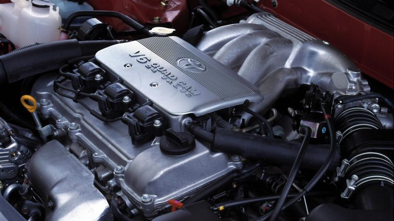
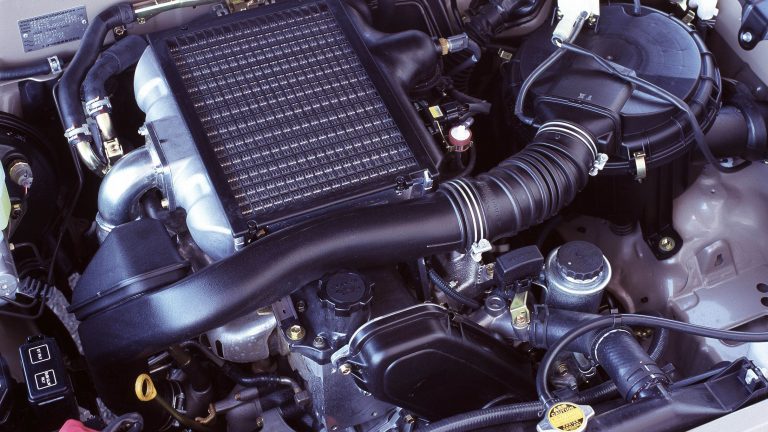
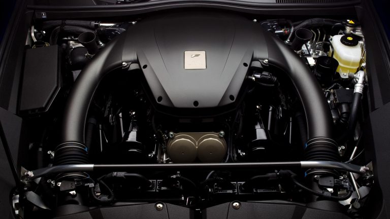
[su_image_carousel source=”media: 52238,52239,52240,52241,52242,52243″]
Introduction
The 3UZ-FE was a 4.3-litre V8 engine that was first introduced in the Lexus XF30 LS 430. An evolution of the 4.0-litre 1UZ-FE engine, the 3UZ-FE had larger bores and revised valve timing. The 3UZ-FE engine was subsequently used in the Lexus S190 GS 430 and Lexus SC 430.
[su_table responsive=”yes”]
| Engine | Trans. | Years | Peak power | Peak torque | |
|---|---|---|---|---|---|
| Lexus XF30 LS 430 | 4.3-litre petrol V8 | 5sp auto | 2000-03 | 207kW at 5600rpm | 417Nm at 3500rpm |
| 6sp auto | 2003-07 | ||||
| Lexus S190 GS 430 | 4.3-litre petrol V8 | 6sp auto | 2005-08 | 208kW at 5600rpm | 417Nm at 3500rpm |
| Lexus Z40 SC 430 | 4.3-litre petrol V8 | 5sp auto | 2001-05 | 210kW at 5600rpm | 419Nm at 3500rpm |
| 6sp auto | 2005-10 |
[/su_table]
3UZ-FE block
The 3UZ-FE had an aluminium alloy cylinder block with a 90 degree ‘V’ angle for the cylinder banks. The 4293 cc 3UZ-FE engine had 91.0 mm bores (expanded from 87.5 mm for the 1UZ-FE) and an 82.5 mm stroke. The bore pitch of 105.5 mm and cylinder bank offset of 21 mm were the same as the 1UZ-FE.
Like the 1UZ-FE, the 3UZ-FE engine had cast-iron cylinder liners, though liner thickness was reduced from 2 mm to 1.5 mm for mass reduction and improved cooling. Furthermore, the thickness of the cylinder walls was increased from 5.5 mm to 6.5 mm, while the shape of the water passage between the bores was optimised to improve cooling performance and rigidity.
Crankshaft, connecting rods and pistons
The 3UZ-FE engine had a forged steel crankshaft with six bolt main bearing caps, five main journals, four connecting rod pins and eight balance weights. For the 3UZ-FE engine, the material on the sliding surface of the crankshaft bearings was changed from kelmet to aluminium alloy.
Whereas most V8 engines have six crankshaft counterweights, the 11UZ-FE and 3UZ-FE V8 engines had eight counterweights. With eight counterweights, each weight was offset 180 degrees from its journal and provided better balance, particularly at higher engine speeds since the centripetal forces generated by any imbalance increase exponentially in proportion to speed. Due to cost, eight counterweight crankshafts are most common in racing engines, and their use in the UZ engines reflected their design being based on a racing CART/IRL engine and planned use in GT500 vehicles. Other race-style design features for the UZ engines included six-bolt cross mains and over square dimensions (bore exceeding stroke).
Like the 1UZ-FE, the 3UZ-FE engine had sintered and forged steel connecting rods with induction-hardened connecting rod pins and journals. In contrast to the 1UZ-FE engine, however, the material of the inner surface of the bushing in the small end of the connecting rod in the 3UZ-FE engine was changed from a lead bronze alloy to a phosphor bronze alloy to reduce the quantity of lead and improve wear resistance.
The 3UZ-FE engine had hypereutectic pistons with steel struts and full floating type piston pins. Furthermore, the sliding surface of the piston skirt was coated with resin to reduce friction. Compared to the 1UZ-FE engine, the position of the piston rings was raised to reduce the area in which unburned fuel may accumulate during the combustion process. While the 3UZ-FE piston heads had a taper squish shape as per the post-1997 1UZ-FE engine, the squish area in the thrust direction of the piston head was omitted and the combustion chamber was made shallower to improve combustion efficiency.
Cylinder head
The 3UZ-FE engine had an aluminium cylinder head with a cross-flow configuration for the intake and exhaust ports. The cylinder head was mounted on a four-layer, steel laminated head gasket that was carried over from the post-1997 1UZ-FE engine, though its shape was changed due to the enlarged cylinder bores.
Belt and gear driven camshafts
Like the 1UZ-FE, the 3UZ-FE engine had double overhead camshafts per cylinder bank (sometimes referred to as ‘quad cam’). The camshafts were made from cast iron and each cam nose was chill treated. The intake camshafts were driven by a timing belt, while the exhaust camshafts were driven by gears on the intake camshaft. For the exhaust camshafts, the scissors gear mechanism used a sub-gear with the same number of teeth as the drive gear and was attached to the gear on the driven side. Through the reaction force of the scissors springs, these two gears acted to pinch the drive gear, reducing backlash to zero and eliminating gear noise.
For the timing belt, an automatic tensioner – which consisted of a spring and oil damper – maintained proper tension at all times. The camshaft journals and camshaft driven gear were lubricated by oil supplied to an oil passage in the centre of the camshaft.
Valves
Like the post-1997 1UZ-FE engine, the 3UZ-FE had four valves per cylinder that were actuated by inner shim type valve lifters that were made from aluminium; the lifters, however, are understood to be both thinner and lighter. The valves were manufactured from high-strength and heat-resistant steel, with a soft nitriding treatment applied to the stem and the face areas of the valves. Valve dimensions, however, were unchanged:
- Intake valve diameter: 34.5 mm;
- Intake valve stem diameter: 5.5 mm;
- Exhaust valve diameter: 29.0 mm; and,
- Exhaust valve stem diameter: 5.5 mm.
Like the 1UZ-FE, the 3UZ-FE engine had a narrow included valve angle of 21 degrees and 33 minutes (i.e. the angle between the intake and exhaust valves).
The valve springs were made from carbon steel and had round-shaped cross sections.
Variable Valve Timing – intelligent (VVT-i)
For the 3UZ-FE engine, the ‘Variable Valve Timing – intelligent’ (VVT-i) controlled intake camshaft timing with a range of 45 degrees relative to crankshaft angle for optimal inlet valve timing. From the table below,
- Intake valve overlap ranged from -11 degrees to 34 degrees (a range of 45 degrees);
- Intake duration was 230 degrees; and,
- Exhaust duration was 229 degrees.
[su_table responsive=”yes”]
| 3UZ-FE Valve Timing: VVT-i | ||
|---|---|---|
| Intake | Open | -14° to 31° BTDC |
| Close | 64° to 19° ABDC | |
| Exhaust | Open | 46° BBDC |
| Close | 3° ATDC | |
[/su_table]The VVT-i controllers were installed on the front of the intake camshafts and included:
- An outer gear that was driven by the timing belt;
- An inner gear that was affixed to the camshaft; and,
- A movable piston that was placed between the outer gear and the inner gear.
With helical splines (twisted, vertical grooves) on its inner and outer sides, the piston moved in the axial direction to shift the phase of the outer gear and inner gear, thus causing valve timing to change continuously. The camshaft timing oil control valve controlled the position of the spool valve position in accordance with signals from the ECM and applied hydraulic pressure to the advance or retard side of the VVT-i controller.
Intake and throttle
Like the 1UZ-FE, the intake for the 3UZ-FE engine featured a dual mode type resonator chamber that was separated by a partition and used to reduce intake air noise. For the 3UZ-FE engine, however, low- to mid-speed torque was improved by extending the length of the intake port.
Like the post-1997 1UZ-FE engine, the 3UZ-FE was fitted with an ‘Acoustic Control Induction System’ (ACIS). ACIS used a bulkhead to divide the intake manifold into two stages with an intake air control valve in the bulkhead that varied the effective length of the intake manifold according to engine speed and throttle valve opening to utilise the effect of inlet pulsations.
The 3UZ-FE also continued to use a heat-barrier gasket – which consisted of a resin sandwiched between metal gaskets – between the cylinder head and the intake manifold to reduce heat transfer from the cylinder head to the intake manifold – this reduced intake air temperature and improved charging efficiency.
The 3UZ-FE engine had electronic throttle control (‘Electronic Throttle Control System – intelligent’ or ETCS-i) which used the ECM to calculate the optimal throttle valve opening according to the driving conditions and used a motor to control the throttle opening. For the 3UZ-FE, however, the accelerator cable was discontinued and an accelerator position sensor was used on the accelerator pedal. The ETCS-i controlled the ISC (Idle Speed Control) system, the cruise control system, the TRAC (Traction Control) system and the VSC (Vehicle Skid Control) system.
Injection and ignition
The 3UZ-FE engine had multi-point sequential electronic fuel injection via four-hole injectors. Air introduced from the throttle body and air gallery flowed through the air chamber that was formed by the O-ring and insulator under the fuel injector; the air was then mixed with the fuel prior to injection. To measure intake air, the 3UZ-FE engine used a plug-in type hot-wire type mass air flow meter.
The 3UZ-FE engine had the Toyota/Lexus ‘Direct Ignition System’ (DIS), an independent ignition system in which there was one ignition coil (with igniter) for each cylinder. In contrast to the 1UZ-FE engine, the 3UZ-FE engine had more compact and lightweight ignition coils. The 3UZ-FE engine also had ‘Electronic Spark Advance’ (ESA) whereby ignition timing was determined by the ECM based on inputs from sensors and adjusted according to knocking. Furthermore, the 3UZ-FE engine had dual knock sensors.
The 3UZ-FE engine had pentroof type combustion chambers with a taper squish design. In the centre of the combustion chamber, there were iridium-tipped spark plugs. Furthermore, the 3UZ-FE engine had a compression ratio of 10.5:1 and firing order of 1-8-4-3-6-5-7-2.
Exhaust
The 3UZ-FE engine had stainless steel exhaust manifolds. Compared to the 1UZ-FE, the 3UZ-FE had shorter front exhaust pipes for faster warm-up performance of the three-way catalytic converters. Furthermore, an ultra thin-wall high-cell ceramic type three-way catalytic converter was adopted.


