
Introduction
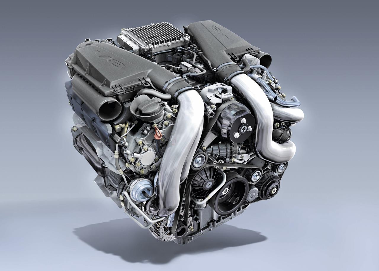
The Mercedes-Benz M278, M157 and M152 were 90-degree V8 petrol engines that were introduced in 2010 to replace the M273 and M156 engines. Specifically,
- M278 referred to the 4.7-litre biturbo V8 engine for Mercedes-Benz vehicles;
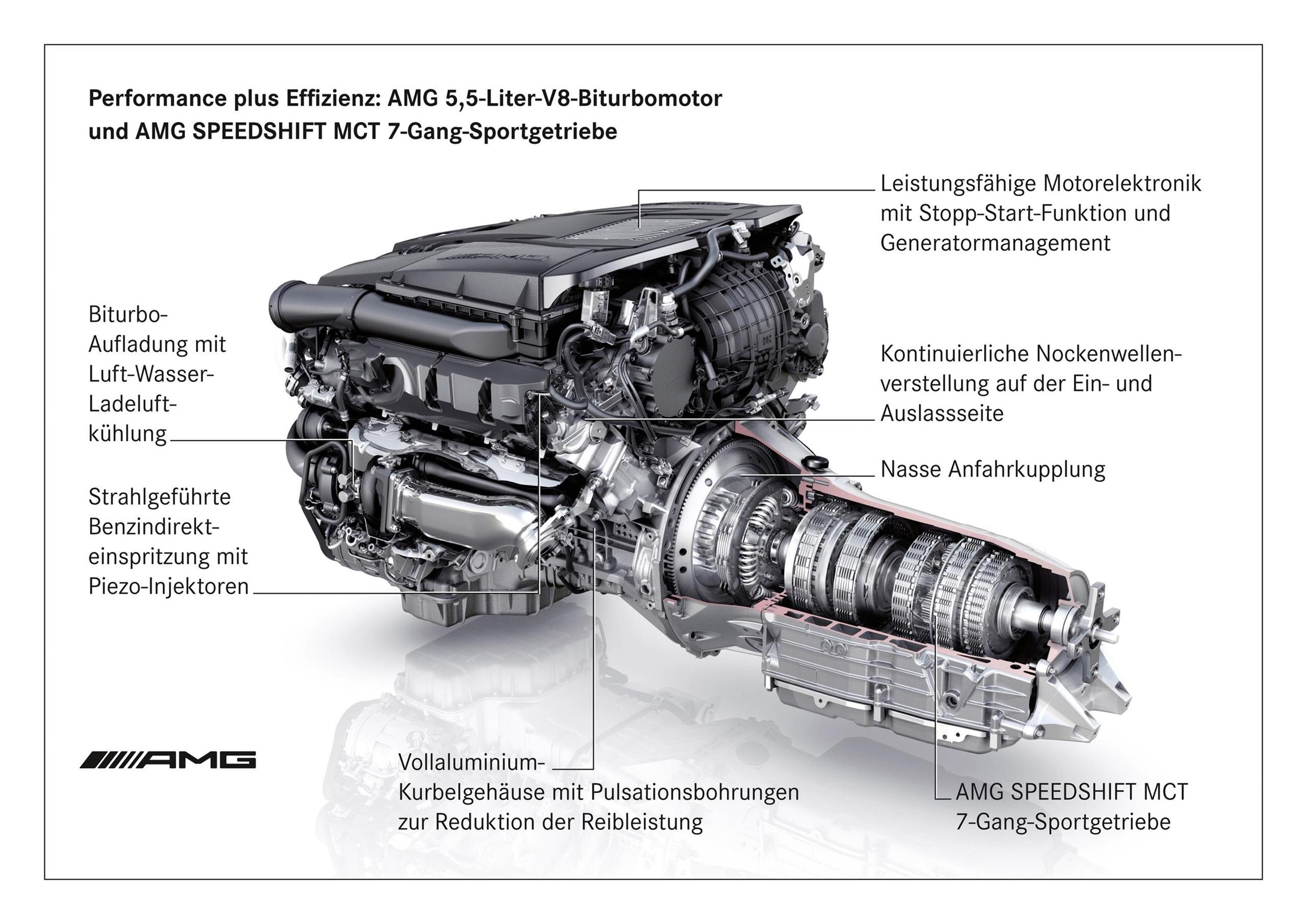
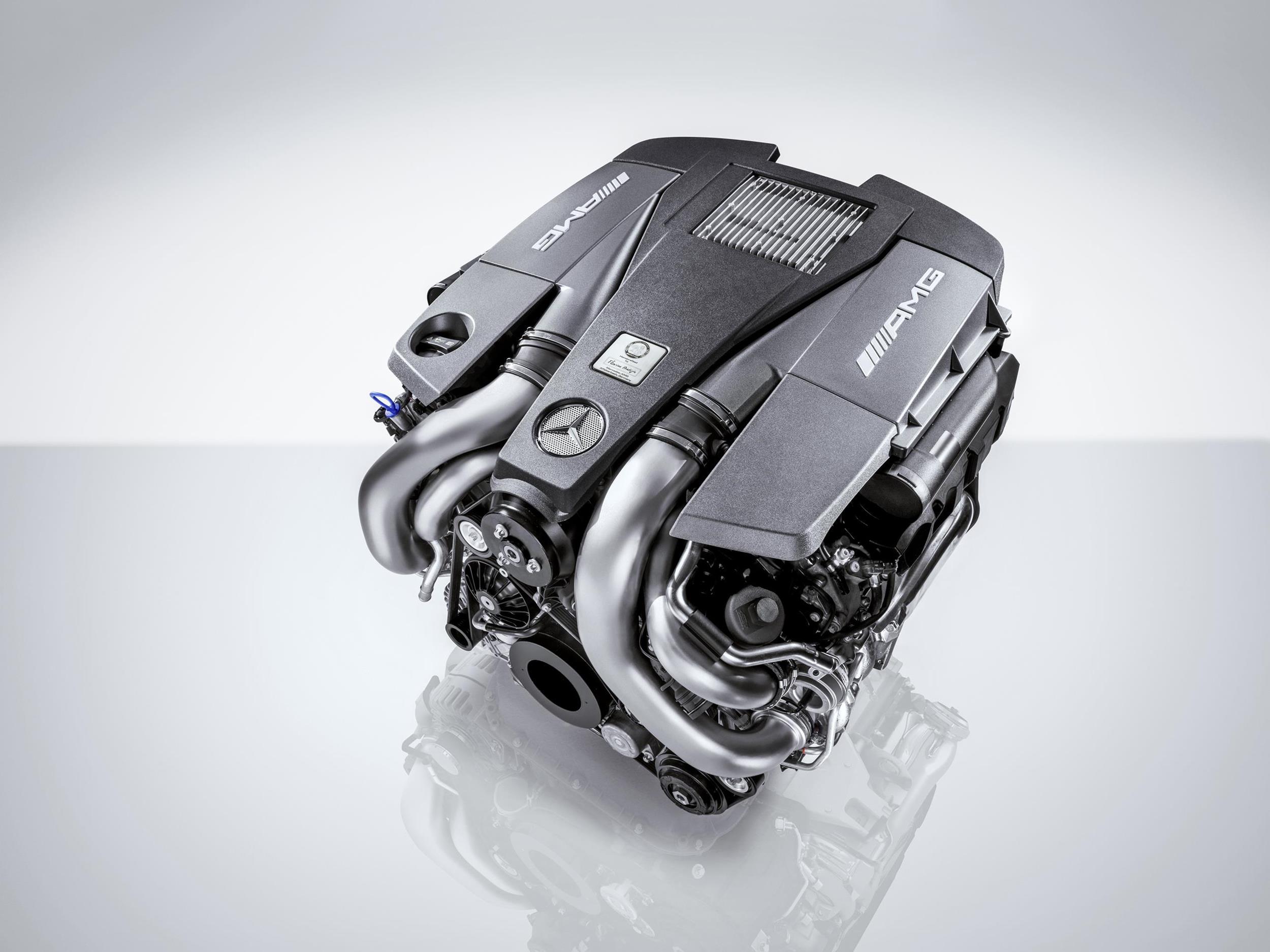
- M157 referred to the 5.5-litre biturbo V8 engine for AMG-badged models; and,
- M152 referred to the 5.5-litre naturally aspirated V8 engine for the Mercedes-Benz R172 SLK 55 AMG (and, subsequently, the Mercedes-AMG R172 SLK 55).
| Engine | M152 AMG | M157 AMG | M278 |
|---|---|---|---|
| Capacity | 5461 cc | 5461 cc | 4663 cc |
| Bore | 98.0 mm | 98.0 mm | 92.9 mm |
| Stroke | 90.5 mm | 90.5 mm | 86.0 mm |
| Cylinder spacing | 106.0 mm | 106.0 mm | 106.0 mm |
| Connecting rod length | 146.5 mm | 146.5 mm | 146.5 mm |
| Piston compression height | N/A | 30.1 mm | 32.35 mm |
| Compression ratio | 12.6:1 | 10.0:1 | 10.5:1 |
| Peak boost pressure | N/A | 1.0 bar (1.3 bar for Performance Package) | 0.9 bar |
| Dry weight | 208 kg | 220 kg | 220 kg |
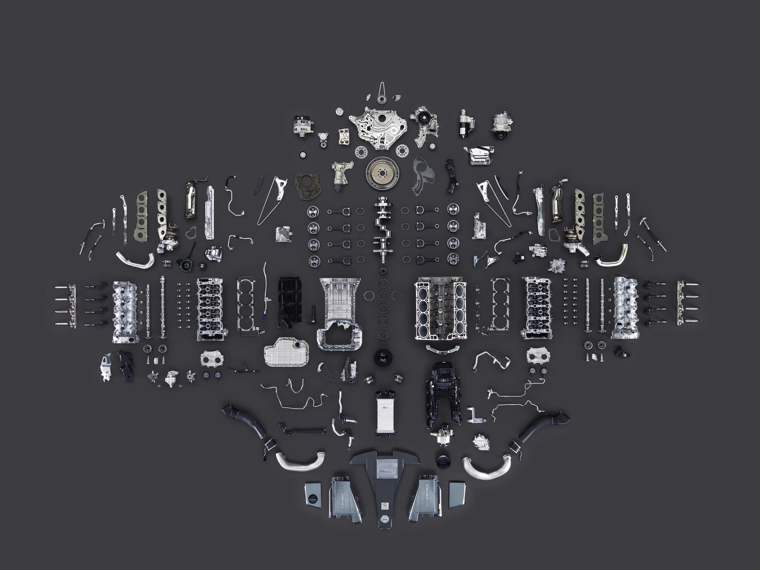
Crankcase
While the M278 engine had 92.9 mm bores and an 86.0 mm stroke for a capacity of 4663 cc, the M152 and M157 AMG engines had 98.0 mm bores and a 90.5 mm stroke for a capacity of 5461 cc. For all engines, however, the cylinders were spaced at 106.0 mm intervals. Within the cylinder bores, the M152, M156 and M278 engines had cast-in Silitec (aluminium-silicon) cylinder liners. The Silitec liners underwent a deck plate honing process which involved mounting a deck stress plate on the cylinder head to simulate the assembled state and associated static deformation of the crankcase.
The ventilation system of the M278, M152 and M157 engines had two oil separators, an impactor on the left cylinder head cover at the front and a centrifuge at the rear of the right cylinder head. While the impactor was a development of the volume separator of the M273 engine, the centrifuge was unchanged.
The crankcase was ventilated via the line between the left air filter and the impactor. In partial load operation, the engine was vented starting at the centrifuge via the pressure regulating valve and the check valve, as well as via the partial-load branch to the charge air distributor. In full-load operation, however, the engine was vented starting at the centrifuge via the pressure regulating valve and the check valve to the right air filter upstream of the turbocharger. Furthermore, full-load venting also occurred via the line between the left air filter and the oil separator to the left air filter upstream of the turbocharger.
Crankshaft, connecting rods and pistons
The M152, M157 and M278 engines had a forged steel crankshaft which had eight counterweights and rotate on five main bearings. Beyond this, these engines had fracture-split forged connecting rods (70MnVS4) and cast aluminium pistons.
For the M152 and M157 AMG engines, the first piston ring had a diamond-like carbon (DLC) coating, a technology adapted from motorsport engines.
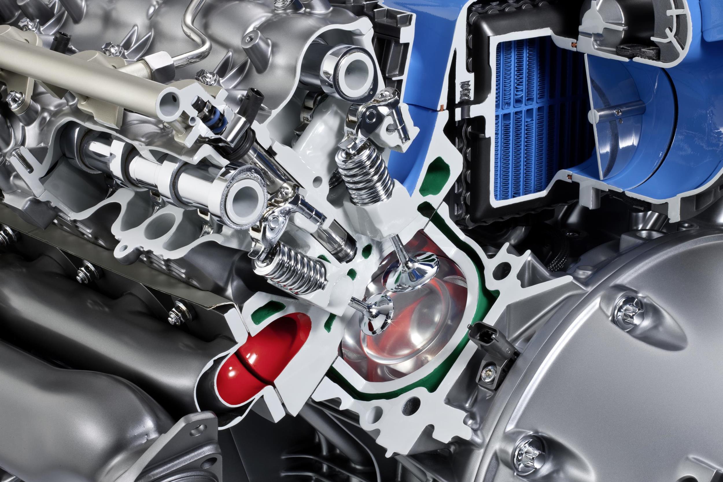
Cylinder head
The M152, M157 and M278 engines had aluminium cylinder heads in which there was a cooling slot between the cylinders. Furthermore, the cylinder head had a two-piece water jacket.
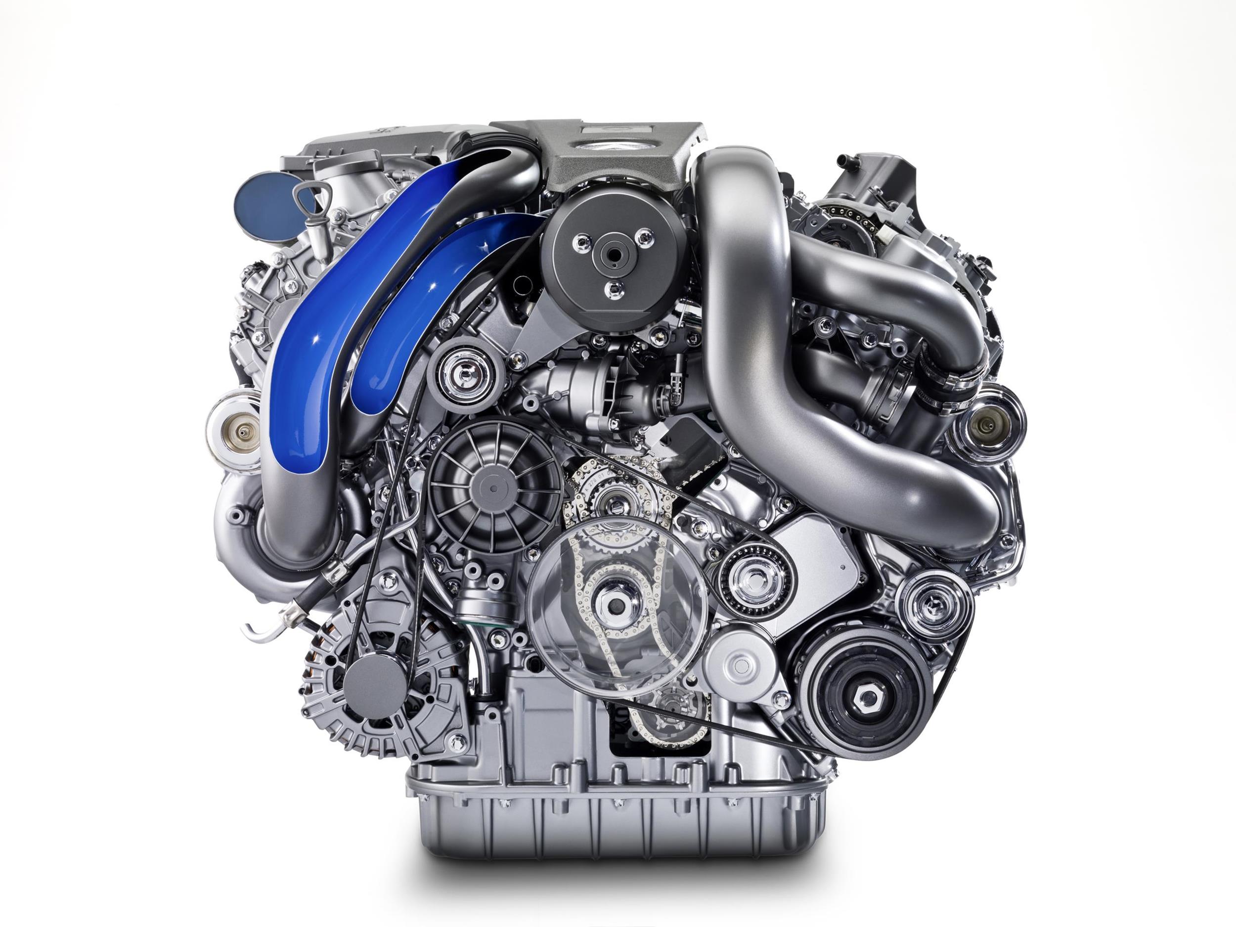
The M152, M157 and M278 engines had double overhead camshafts that were drive by a two-stage chain drive with three gear chains; each of the three gear chains was tensioned by a hydraulic chain tensioner. For the M152 and M157 AMG engines, the camshafts were made from an internal high-pressure formed (IHPF) steel tube with composite cams.
Like the related M276 V6 engine, the M278, M152 and M157 AMG engines had hydraulic vane-cell camshaft adjusters with integrated control valve for fast and stepless operation. The camshaft adjuster was capable of adjusting all four camshafts steplessly by up to 40 crank angle degrees (i.e. relative to the crankshaft) to vary valve overlap. Intake valve opening (IO) could be varied from 4 degrees BTDC to 36 degrees ATDC, while exhaust valve closing (EC) could be varied from 25 degrees BTDC to 15 degrees ATDC. On start-up, the camshafts were locked in a fixed position by a catch bolt and this start position was unlocked hydraulically the first time the intake camshaft and exhaust camshaft solenoids were actuated.
The four valves per cylinder were actuated by roller cam followers. For the M152 and M157 AMG engines, the hollow exhaust valves were filled with sodium for heat dissipation.
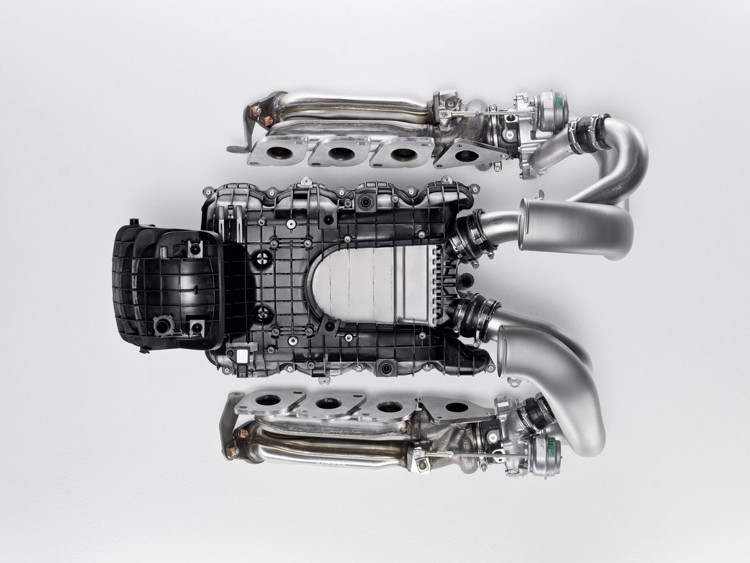
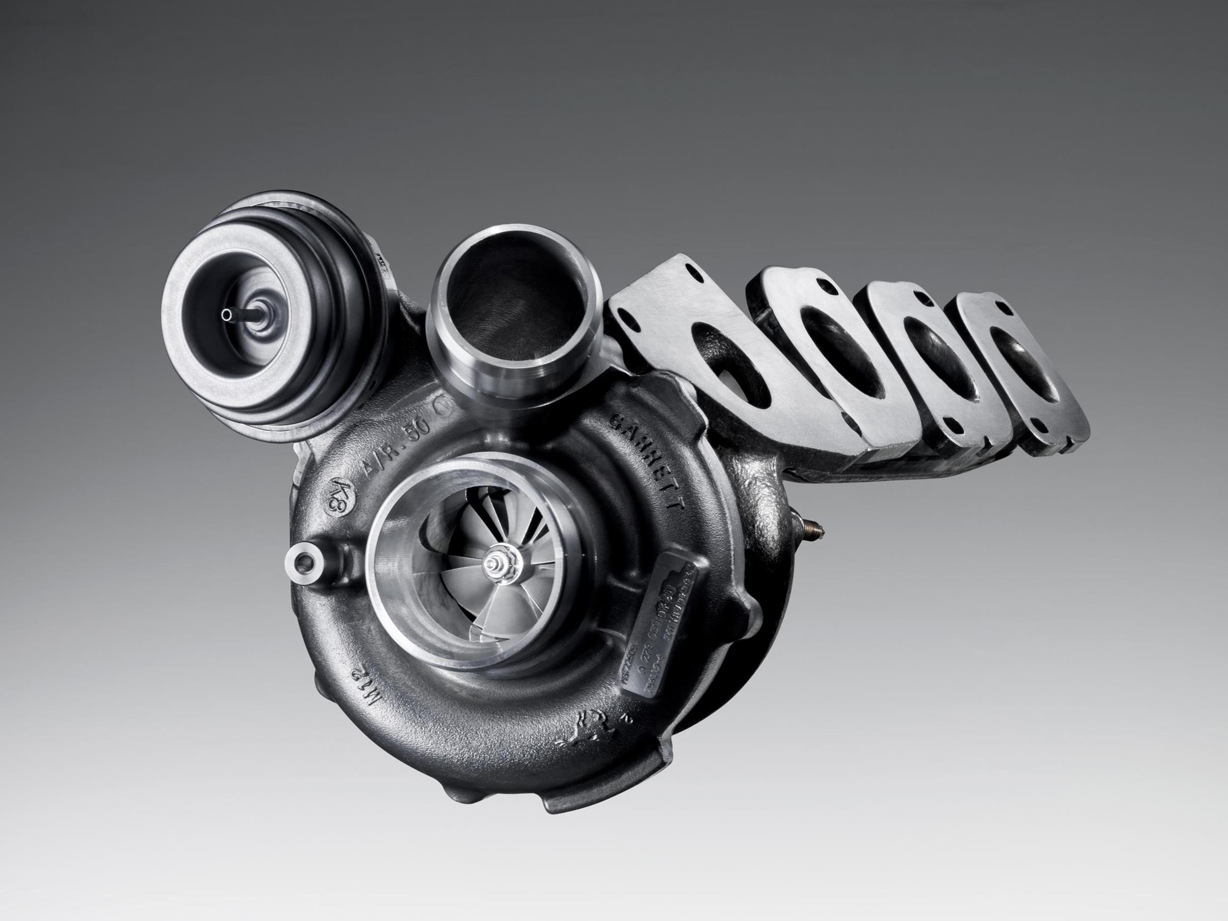
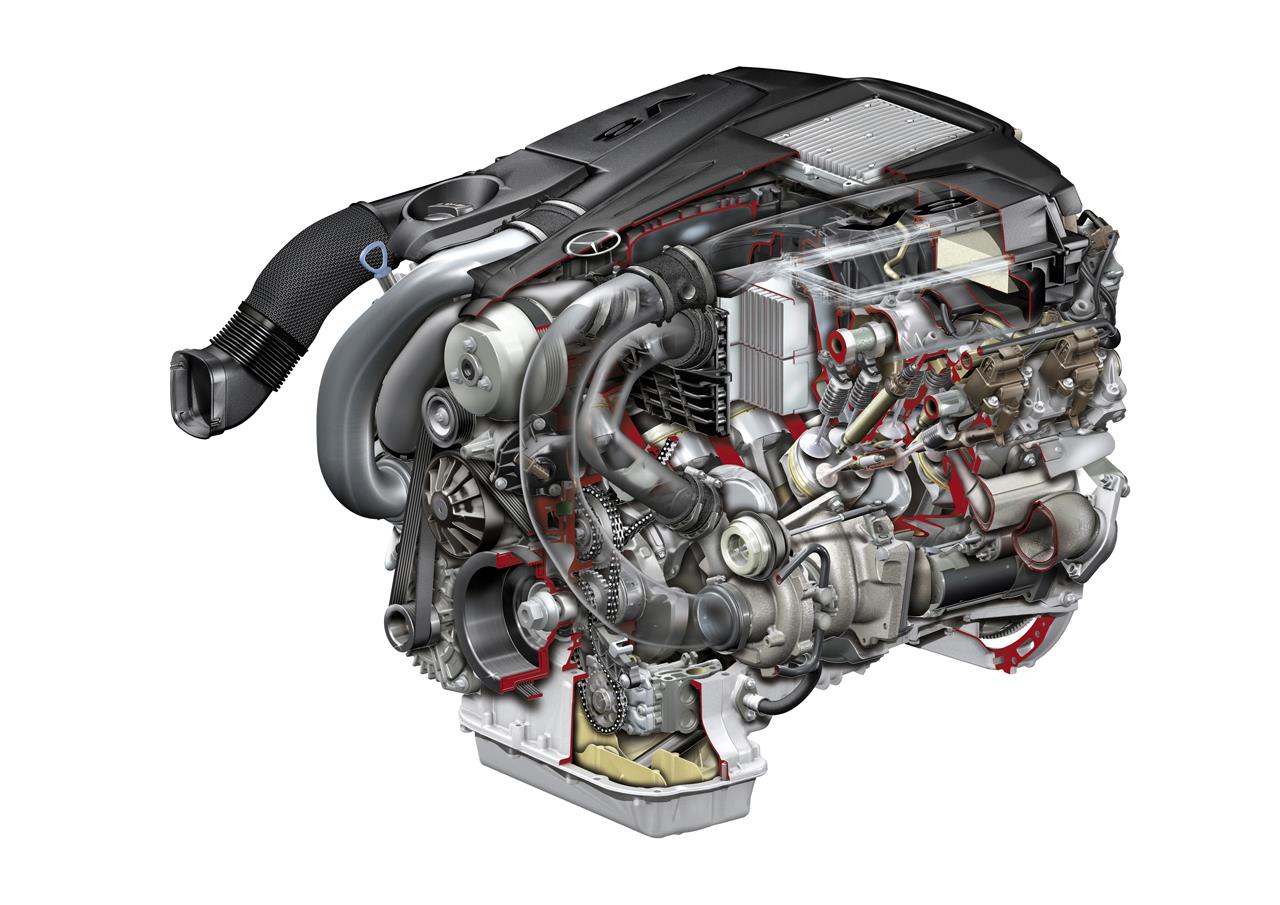
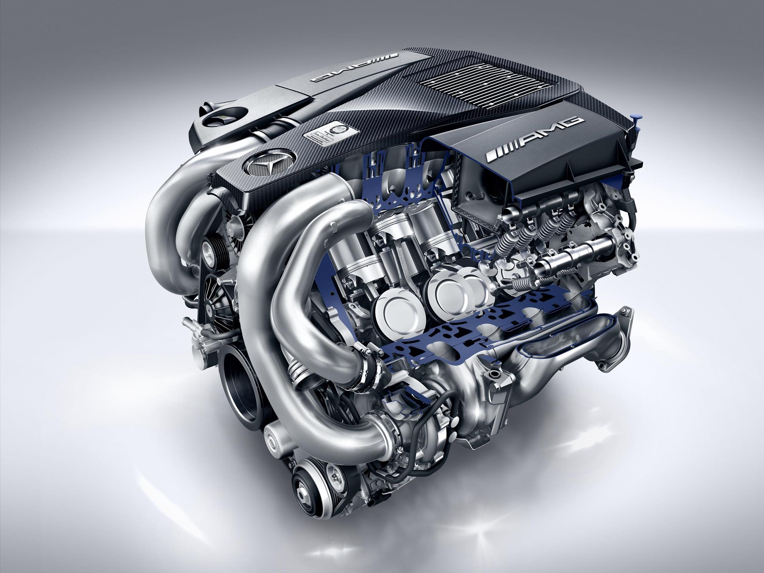
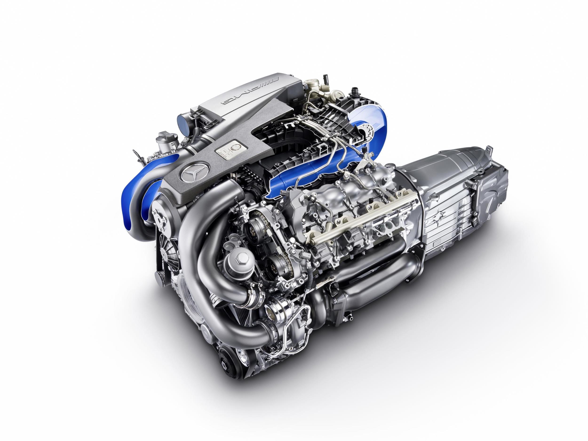
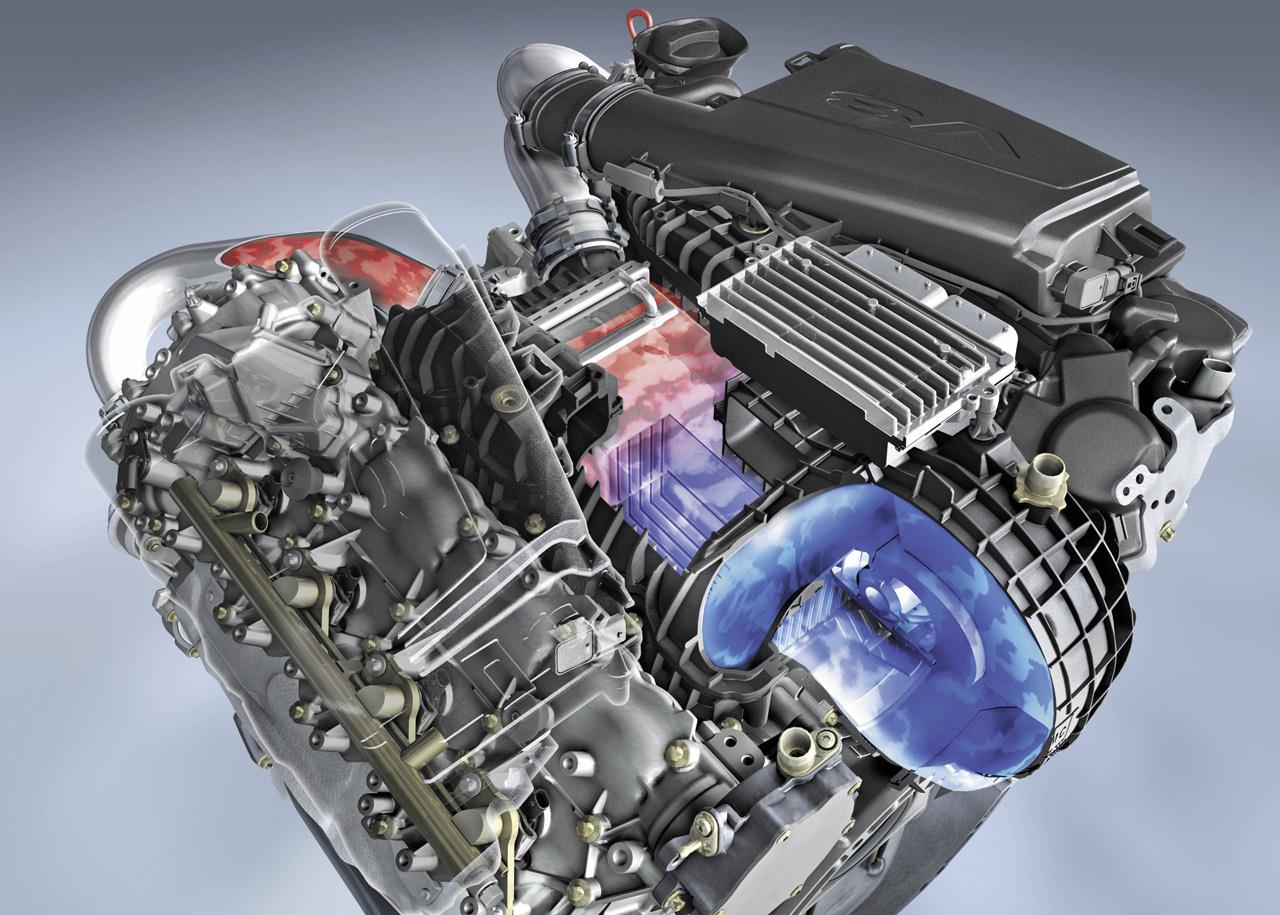
Turbocharging (M278 and M157 AMG)
For the M278 and M157 AMG engines, each of the two cylinder banks had a turbocharger with wastegate control that was positioned within the cylinder banks (i.e. inside the engine’s ‘V’). Each of the two exhaust manifolds was fitted with a turbocharger that was driven by the thermal and kinetic energy of exhaust gases from the associated cylinder bank. In turn, the exhaust gas was carried in an air gap-insulated, welded exhaust manifold and an exhaust pipe downstream of the turbocharger.
Of these engines,
- The M157 AMG engine had Garrett MGT2260MSL turbochargers which provided peak boost pressure of 1.0 bar (1.3 bar for the Performance Package); and,
- The M278 engine had Garrett MGT1752SM turbochargers which provided peak boost pressure of 0.9 bar.
To regulate boost pressure, the wastegate was controlled by a vacuum from the mechanical vacuum pump mounted on the engine. As such, the wategate could be opened in the partial-load range to reduce fuel consumption and, to accumulate boost pressure, the wastegate would be closed by a vacuum from the vacuum unit. To reduce boost pressure, the exhaust streams which drove the turbocharger turbines would be diverted via different bypasses by opening the boost pressure control flaps.
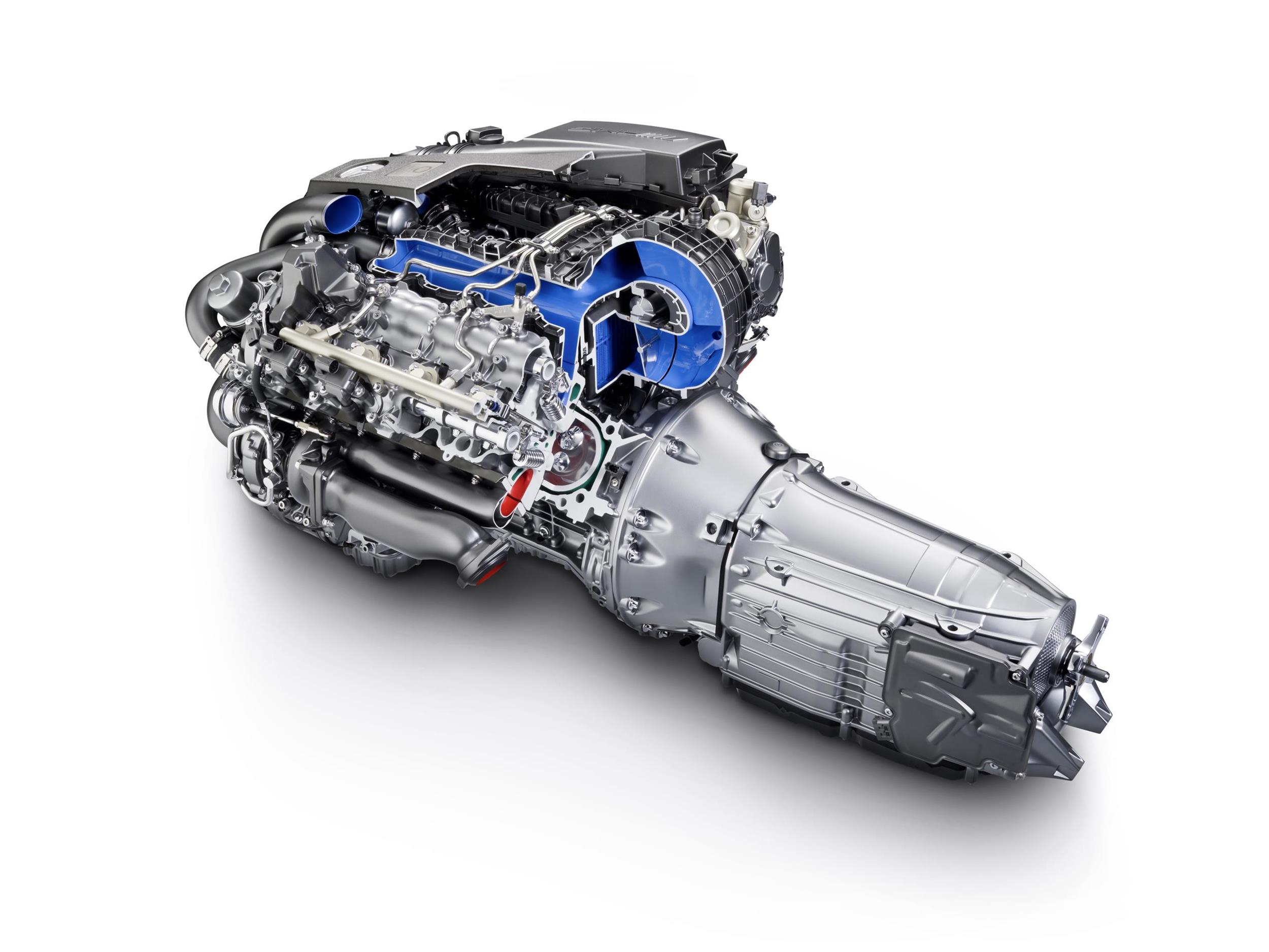
Charge air cooling (M278 and M157 AMG)
For the M278 and M157 AMG engines, the two cylinder banks had a common water/charge air cooler that was connected to the low-temperature cooling circuit with low-temperature cooler and charge air cooler circulation pump. If charge air temperature exceeded 35 degrees Celsius, the charge air cooler circulation pump would be actuated by the ME-SFI control unit via the circulation pump relay. Beyond this, the charge air cooling system kept the charge air at below 70 degrees Celsius. When charge air temperature was below 25 degrees Celsius, however, the charge air cooler circulation pump would be switched off.
By cooling the charge air, it had greater density for power production, reduced the tendency to knock (i.e. uncontrolled detonation) and reduced the formation of nitrogen oxides.
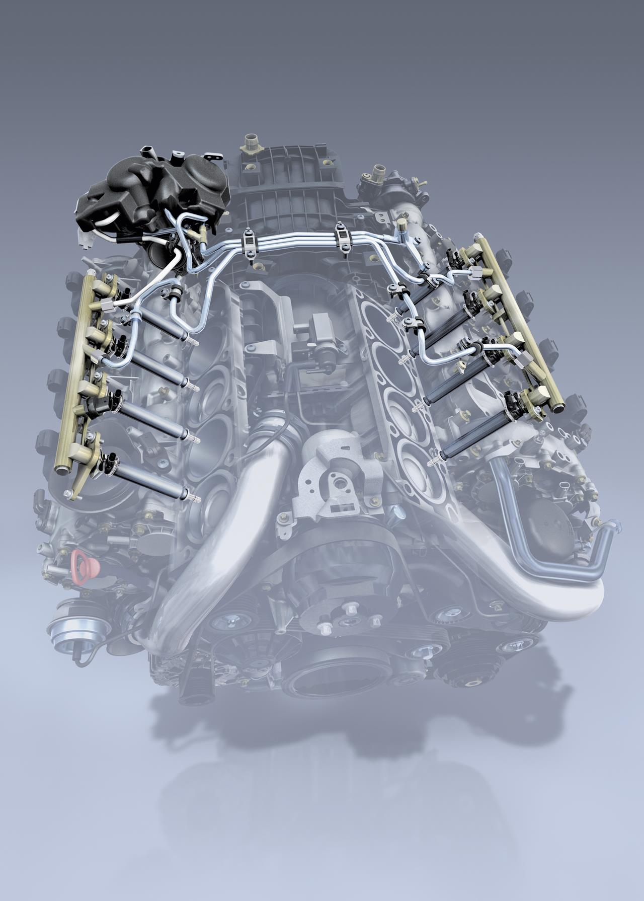
Fuel supply
For the M278, M152 and M157 AMG engines, fuel pressure from the low-pressure fuel pump varied from approximately 4.5 to 6.7 bar depending on the requirements. When actuated, the fuel pump drew fuel from the fuel feed module and pumped it through the fuel filter; at a pressure of 7 to 9 bar, the overflow valve in the fuel filter would open. Fuel from the low-pressure fuel pump distributor would then flow to the high-pressure fuel pump – located at the rear end of the right intake shaft and actuated by three cams – to generate the pressure necessary for spray-guided direct injection. Depending on the operating state, the high-pressure pump would compress the fuel to 100-200 bar depending on operating mode; the fuel would then be directed through the high-pressure line and the fuel rails to the fuel injectors.
Direct injection
The M278 engine had a third-generation direct injection system with a non-return high-pressure supply with two separate fuel rails. From the rail, the piezo injectors sprayed finely atomised fuel into the combustion chambers and were capable of delivering up to five injections per cycle. A coupler module inside each fuel injector ensured that the nozzle module and the piezo actuator module had zero clearance in the longitudinal direction. The fuel feed was sealed on the high-pressure side with an O-ring at the rail. Another O-ring at the fuel injector sealed the leak line. Furthermore, the seal between the fuel injector and the cylinder head was provided by a Teflon ring.
Multi-spark ignition
The M278 engine had single- and multi-spark ignition modes. In the standard single-spark ignition mode, the ignition coil would charge to a target primary current and, at firing point, the charging current would be shut off to produce a spark.
In multi-spark mode, however, the coil would not be completely discharged and the secondary current – which was dependent on the charge level of the coil – would be measured in the coil. If the secondary current dropped below a threshold, the coil’s electronic control would re-open the power amplifier to allow charging current to flow, while the level of the primary current would also monitored. When the primary current threshold was reached, the power amplifier would close the primary circuit and high voltage would be generated again, causing another spark to be produced. Subsequent sparks were also produced in the same manner.
Multi-spark ignition could achieve up to four successive sparks (within one millisecond) to create a plasma which provided greater spatial expansion than conventional ignition. As such, it was possible to use a much leaner mixture with stratified combustion and reduce fuel consumption.
ECO start/stop
The M278, M152 and M157 AMG engines had a start-assisted in-engine direct start function and an engine stop function which combined to form a start/stop function. With the selected piezo injection valve coupled with the correct injection timing, the very first compression stroke of a cylinder could be utilised for a controlled combustion. Furthermore, the cylinder with the most favourable piston position would receive the injection of fuel into its combustion chamber. To drive off immediately after a direct start of the engine, however, the oil supply to the transmission hydraulics had to be maintained while the engine was off and while it was being restarted. As such, the additional electric transmission oil pump supplied oil to the transmission control system when the internal transmission pump is off.
The ECO start/stop function also utilised an additional 12 Ah battery which ‘cushioned’ the voltage drop during engine starts. Specifically, the additional battery supplied power to all active consumers while the regular battery was decoupled from the on-board electrical system and made available solely to the starter.
Cylinder deactivation (M152 only)
Although not turbocharged, the M152 engine had a cylinder deactivation function that enabled four cylinders to shut down under low throttle loads.
For the M152 engine, a cylinder shut-off function was available at low loads from 800 rpm to 3600 rpm if the driver had selected the ‘Controlled Efficiency’ (C) transmission mode. To facilitate shut-off of cylinders 2, 3, 5 and 8,
- Fuel injection and fuel ignition would be adjusted; and,
- The intake and exhaust valves would be closed. To achieve this, switchable hydraulic pivot elements in the cylinder heads would drop below the camshaft and disconnect the valves from the camshaft. As such, the cylinder head had complex oil supply bores for the hydraulic pivot elements.
Shutting down cylinders increased efficiency by shifting the operating point of the active cylinders to higher loads and reducing gas cycle losses.
In response to accelerator pedal inputs, the shut-off cylinders would be reactivated ‘quickly and with neutral torque effect, so that ride comfort is not compromised.’ At an engine speed of 3600 rpm, the re-activation process would occur in ‘no more than 30 milliseconds’
To reduce vibrations, a centrifugal pendulum was integrated in the torque converter of the AMG SPEEDSHIFT PLUS seven-speed automatic transmission. The centrifugal pendulum acted as an rpm-adaptive damper which operated across the entire engine speed range
Ancillaries and lubrication
To reduce energy demand, the M278, M152 and M157 AMG engines had efficient ancillary units such as:
- An optimised water pump with second generation thermal management;
- A newly developed vane-type oil pump with on-demand quantity control and two map-controlled, switched pressure levels. At the high pressure level, the lubrication and cooling points in the engine were supplied with the maximum quantity of oil at 4 bar. At the low level, however, the flow rate was reduced to 2 bar and the oil sprayers for cooling the piston undersides were also shut off;
- A volume-controlled high-pressure fuel pump; and,
- A variable alternator.
| Engine | Capacity | Peak power | Peak torque | Models |
|---|---|---|---|---|
| M152 DE 55 | 5461 cc (98.0 x 90.5) |
310 kW at 6800 rpm | 540 Nm at 4500 rpm | R172 SLK 55 AMG |
| M157 DE 55 AL | 5461 cc (98.0 x 90.5) |
386 kW at 5500 rpm | 700 Nm at 1700-500 rpm | W166 ML 63 AMG, W212 E 63 AMG, C218 CLS 63 AMG |
| 395 kW at 5500 rpm | 800 Nm at 2000-4500 rpm | R231 SL 63 AMG | ||
| 400 kW at 5500 rpm | 800 Nm at 2000-4500 rpm | C216 CL 63 AMG, W212 E 63 AMG, C218 CLS 63 AMG |
||
| 415 kW at 5500 rpm | 900 Nm at 2250-3750 rpm | R231 SL 63 AMG (Performance Package) |
||
| 420 kW at 5500 rpm | 900 Nm at 2000-4500 rpm | C216 CL 63 AMG (Performance), W221 S 63 AMG (Performance) |
||
| 430 kW at 5500 rpm | 800 Nm at 1700-5000 rpm | W212 E 63 AMG 4MATIC S, C218 CLS 63 AMG 4MATIC S |
||
| 430 kW at 5500 rpm | 900 Nm at 2250-3750 rpm | C217 S 63 AMG , W222 S 63 AMG |
||
| M278 DE 46 AL red. | 4663 cc (92.9 x 86.0) |
270 kW at 5250 rpm | 460 Nm at 2700-5000 rpm | X166 GL 450 |
| 300 kW at 5250 rpm | 460 Nm at 2700-5000 rpm | W166 ML 500, W212 E 500, C218 CLS 500 |
||
| M278 DE 46 AL | 4663 cc (92.9 x 86.0) |
320 kW at 5250 rpm | 700 Nm at 1800-3500 rpm | X166 GL 500, C216 CL 500, W221 S 500, R231 SL 500 |
| 335 kW at 5250 rpm | 700 Nm at 1800-3500 rpm | C217 S 500, W222 S 500 |
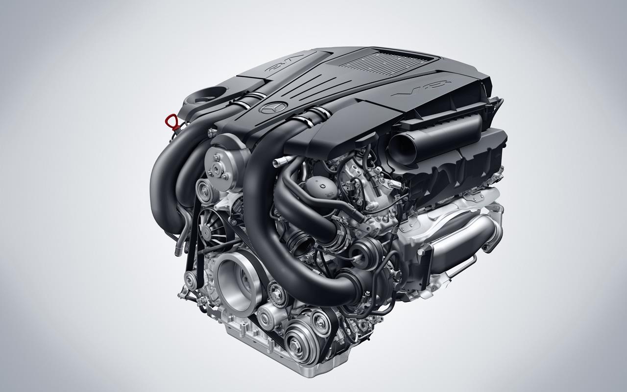
Mercedes-Benz M152 V8 engine
Mercedes-Benz M157 V8 biturbo engine