[su_image_carousel source=”media: 51125,51126,51127,51128,51129,51130,51131″]
Introduction
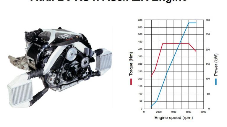
Audi’s ASJ and AZR engines were 2.7-litre biturbo V6 petrol engines that powered the Audi B5 RS4. Key features of the ASJ/AZR engine included its:
- Cast iron block with 90-degree ‘V’ angle;
- Die-forged steel crankshaft;
- Forged pistons;
- Cast aluminium alloy cylinder head;
- Double overhead camshafts;
- Five valves per cylinder actuated by hydraulic tappets;
- Variable intake camshaft timing over a range of 22 degrees relative to the crankshaft;
- Parallel BorgWarner K04 turbochargers which provided peak boost pressure of 1.2 bar;
- Electronic throttle control;
- Compression ratio of 9.0:1;
- Bosch Motronic ME 7.1 engine management system;
- Maximum engine speed of 7200 rpm.
The ASJ/AZR engine had a service weight of approximately 200 kg.
Difference between ASJ and AZR engines
While the ASJ engine complied with Euro II emissions standards, the AZR engines complied with Euro III emissions standards and were fitted with Euro On-Board Diagnosis (EOBD). For the AZR engine, the engine control unit could detect faults that adversely affected exhaust emissions and inform the driver by illuminating the exhaust gas warning lamp. If the engine control unit detected misfires that could damage the catalytic converters, the exhaust gas warning lamp would flash.
[su_table responsive=”yes”]
| Model | Engine | Trans. | Peak power | Peak torque |
|---|---|---|---|---|
| Audi B5 RS4 | 2.7-litre ASJ/AZR biturbo petrol V6 | 6sp man. | 280kW at 6100-7000rpm | 440Nm at 2500-6000rpm |
[/su_table]
Block
The ASJ/AZR engine had a grey cast iron block with 81.0 mm bores that were spaced 88.0 mm intervals; the engine also had an 86.4 mm stroke for a capacity of 2671 cc.
Crankshaft, connecting rods and pistons
The ASJ/AZR engine had a die-forged steel crankshaft that was supported by four main bearings. Relative to the AZB/AGB engine, however, the steel for the ASJ/AZR crankshaft had a ten per cent higher load capability.
For the ASJ/AZR engine, the bearing caps were reinforced and made of cast steel. Like the AZB/AGB engine, however, they were attached to the central crankcase by four bolts, while the middle two crankshaft bearing caps were also bolted to the side of the crankcase. For the ASJ/AZR engine, reinforcement of the crank assembly was necessary to absorb the high power output and the associated inertia forces exerted on the crankshaft bearings.
For the ASJ/AZR engine, the size of the connecting rod bolts was increased from M8.5 to M9 to withstand the increased inertia forces.
While the ASJ/AZR engine had forged pistons like the AZB/AGB engine, changes included:
- A reinforced piston crown area and piston pin bushings;
- The inner surface of the first piston ring groove was hard anodised;
- The piston ring had a PVD coating (vapour deposition of a wear-resistant compound in a nitrogen atmosphere); and,
- Longer piston pins with increased diameter.
Cylinder head
The cylinder head of the ASJ/AZR engine was cast from a warm-hardened aluminium alloy and designed for high loads. To achieve precision sand-cast parts with a highly durable, microporous material structure, the casting process was developed in cooperation with Cosworth Technologies. Relative to the AZB/AGB engine, the cylinder head had additional ventilation channels.
The ASJ/AZR engine had double overhead camshafts that were driven by a toothed belt and simplex chain. The intake camshaft provided variable intake valve timing and had an adjustment range of 22 degrees relative to the crankshaft.
The ASJ/AZR engine had five valves per cylinder: three intake valves and two exhaust valves. For heat dissipation, the exhaust valve stems were filled with sodium. The valves were actuated by maintenance-free, ‘matched’ hydraulic tappets for minimal oil leakage in the valve gear. In the matching process, the tappet bores and tappets were measured individually, with the tappets then selected according to specified valves prior to assembly; this process kept tolerances within acceptable limits.
For the ASJ/AZR engine, the material of the exhaust valve seat rings was changed for improved thermal conduction and to lower component temperatures. Furthermore, coolant flow was optimised area the exhaust valves to limit thermal loading.
Like the AZB/AGB engine, the ASJ/AZR engine did not have a variable intake manifold or tumble flaps. Changes for the ASJ/AZR engine, however, included:
- Adapted tumble intake ports for higher flow rates;
- Reduced outlet diameter exhaust ports; and,
- The critical wall sections in the intake ports – where fuel particles could lead to undesirable fuel enrichment – were also reduced.
On top of the cylinder head, the ASJ/AZR engine had a three-piece carbon-fibre engine cover.
BorgWarner K03 turbochargers
The ASJ/AZR engine had two water-cooled, parallel BorgWarner K04 turbochargers (one per cylinder bank) and two side-mounted charge air cooler (or intercoolers, detailed below). Whereas the Audi B5 S4‘s AZB/AGB engine had BorgWarner K03 turbochargers, the Audi RS4 had larger BorgWarner K04 turbochargers which provided maximum charge pressure of 1.2 bar (17.4 psi). For the AZB/AGB engine, changes included:
- Due to higher temperatures and mechanical loads, a different material for the turbine housing; and,
- The increased pressure conditions required a larger turbine-housing connecting surface for sealing purposes.
[su_table responsive=”yes”]
| Audi B5 S4 | Audi B5 RS 4 | |
|---|---|---|
| Turbocharger | BorgWarner K03 | BorgWarner K04 |
| Compressor wheel (diameter, mm) | 46.0 | 51.0 |
| Turbine wheel (diameter, mm) | 45.0 | 50.0 |
[/su_table]The turbochargers were flanged directly onto the exhaust manifold to minimise the distance that the exhaust gases had to travel and reduce temperature losses. Furthermore, the catalytic converters were able to reach operating temperature more quickly. According to Audi, positioning the turbochargers outside of the engine’s ‘V’ also avoided additional heating of the charged air and thermal stress on the sub-assemblies.
Fresh air was induced by the combined air filter and air mass meter and then distributed to the two exhaust gas turbochargers by the air distributor. Once compressed by the turbochargers, the air was fed to the charge air coolers (intercoolers).
Both the turbochargers were water-cooled and integrated in the cooling circuit which used an electric pump. When the coolant thermostat was closed, coolant flowed back to the coolant pump along the short-circuit line and the heat exchanger. When the coolant thermostat was open, however, coolant flowed back to the thermostat through the radiator (primary flow) or through the oil cooler and expansion tank (secondary flow).
Charge pressure control
The air mass required to develop a specific level of torque was determined by an air mass calculation and produced by controlling the charge pressure as required. The Bosch Motronic ME 7.1 engine management system regulated charge pressure of both turbochargers via the solenoid valve for charge pressure control. The purpose of charge pressure control was to prevent an excessively high charge pressure from accumulating in the intake system.
To avoid pumping the turbochargers when a sudden transition was made from high load to over-run, two divert air valves were used. The Bosch Motronic ME 7.1 engine management system could activate the divert air valves via an electrical changeover valve.
Charge pressure cooler (intercooler)
The charge air coolers received cooling air from air intakes in the bumper and air vents in the wheel housing liners. The charge air coolers increased the density of the intake air for greater efficiency and the lower temperature also suppressed knocking. The compressed air streams then converged upstream of the throttle valve control part and were distributed to the individual cylinders in the intake manifold.
Since the air requirement of the ASJ/AZR engine could be as high as 1200 kg/h, the charge air cooler and associated components were adapted:
- Relative to the AZB/AGB engine, the air cooler cross sections were enlarged by 37 per cent and the air-cooled surfaces by 16 per cent;
- The moulded rubber parts between the intake and pressure sides were replaced by more flexible designs due to spatial and pressure considerations;
- Aluminium was required for the lower and upper headers to accommodate the increased pressure conditions downstream of the turbochargers; and,
- Due to the increased loads, the pressure-side pipe ends were made from aluminium rather than plastic.
Other changes included:
- An increased diameter air mass meter;
- For the intake manifold, an enlarged swivel tube diameter;
- A larger aluminium throttle valve flange;
- Cast aluminium air ducts (previously plastic); and,
- Increased diameter air pipes minimised pressure losses.
Injection and ignition
Each cylinder bank was fitted with a fuel rail which had special dual-jet injectors positioned at an inclination of 13 degrees (relative to the central axis of the valves). From there, the ASJ/AZR engine used electronically controlled, multi-point sequential fuel injection with Siemens fuel injectors.
The injection and ignition process was controlled by the Bosch Motronic ME 7.1 system. Furthermore, the ASJ/AZR engine had a compression ratio of 9.0:1 and 1-4-3-6-2-5 firing order.
Cooling
For the ASJ/AZR engine, the oil circuit was adapted to the higher engine speeds. To prevent excessive foaming of the oil at higher engine speeds, the ASJ/AZR engine has increased diameter oil return ducts. Oil returning from the cylinder heads was guided along the partition wall and via the baffle plate, below the dynamic oil level and into the sump. As a result, degassing of the oil could occur more readily and turbulence from the crank drive was prevented.
To supply sufficient oil to the circuit, the oil pump had an increased tooth width. Furthermore, serially connected heat exchangers compensated for higher pressure losses in certain operating conditions.
To maintain engine oil temperature within the range specified, an additional oil cooler was fitted below the main cooler. If engine oil temperature exceeded 120 degrees Celsius, the flow rate was increased by the thermostat element to keep oil temperatures below the maximum of 135 degrees Celsius.
Crankcase breather
The ASJ/AZR engine had a crankcase breather which consisted of a distributor piece, a pressure limiting valve, a non-return valve and the associated hoses. Specifically,
- The oil vapours and ‘blow-by’ gases from the cylinder heads and the crankcase converged in the distributor piece; and,
- The pressure limiting valve and the non-return valve controlled the return of these vapours and gases to the engine, depending on intake manifold pressure
Exhaust and emissions
Both the ASJ and AZR engines had two primary catalytic converters near the engine, two underfloor main catalytic converters and cylinder-bank selective lambda probe controls with two heated lambda probes.
The ASJ/AZR engine had a secondary air injection system so that the catalytic converters reached their operating temperature faster. In this process, the fuel mixture was enriched to produce a higher percentage of unburnt hydrocarbons in the exhaust gas. The secondary air injection – located downstream of the exhaust valves – then enriched the exhaust gases with oxygen, causing oxidation (i.e. after-burning) of the hydrocarbons and carbon monoxide.


