[su_image_carousel source=”media: 51236,51237,51238,51239,51240″]
Introduction
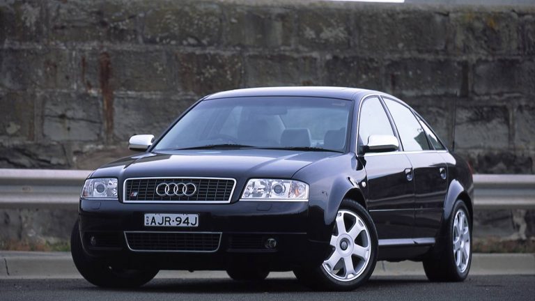
Audi’s AQJ and ANK were 4.2-litre V8 petrol engines that powered the Audi C5 S6. Key features of the AQJ/ANK engines included:
- A cast aluminium alloy block with 90-degree ‘V’ angle;
- Die-forged steel crankshaft with five main bearings;
- Cast aluminium alloy cylinder head;
- Double overhead camshafts driven by a toothed belt and simplex chain;
- Five valves per cylinder actuated by roller rocker cam followers;
- Variable intake camshaft timing;
- A variable intake manifold;
- Electronic throttle control;
- A compression ratio of 11.0:1;
- Maximum engine speed of 7200 rpm; and,
- Mass of 200 kg.
The AQJ was replaced by the ANK in August 2000. Compared to the AQJ, the ANK differed in that its emissions control system had four heated oxygen sensors – rather than the two of the AQJ – which also necessitated changes to the Bosch Motronic ME 7.1 engine management system. Both engines, however, complied with Euro III emissions standards.
[su_table responsive=”yes”]
| Model | Engine | Years | Trans. | Peak power | Peak torque |
|---|---|---|---|---|---|
| Audi C5 S6 | 4.2-litre AQJ petrol V8 | 2001 | 5sp auto | 250kW at 7000rpm | 420Nm at 3400rpm |
| Audi C5 S6 | 4.2-litre ANK petrol V8 | 2001-04 | 5sp auto | 250kW at 7000rpm | 420Nm at 3400rpm |
[/su_table]
Cylinder block
The AQJ/ANK engine had a cast aluminium alloy block with 84.5 mm bores and a 93.0 mm stroke for a capacity of 4172 cc. The die-forged steel crankshaft was supported by five main bearings and, attached to the crankshaft, the 40 valve V8 engine had forged connecting rods.
It is understood that the AQJ/ANK had cast aluminium alloy pistons with specially-designed valve recesses.
Cylinder head
The AQJ/ANK engine had cast aluminium alloy cylinder head that was mounted on a triple-layer metal gasket. The double overhead camshafts were driven by a toothed belt and simplex chain and used roller cam followers – with hydraulic adjustment – to actuate the five valves per cylinder (three intake and two exhaust).
The 4.2-litre AQJ/ANK engine had variable intake camshaft timing.
Roller rockers
To minimise inertia forces and facilitate the 7200 rpm maximum engine speed, the roller rockers were made of die-cast aluminium. Compared to the mechanical bucket tappets of Audi’s 32 valve V8 engine, the roller rockers reduced frictional losses in the valvegear and halved the oil delivery rate in the cylinder heads. The rockers were supported by a spindle shaft which was also used to supply oil to the bearings and the hydraulic valve lifters. Valve actuation, however, differed between intake and exhaust valves:
- The two exhaust valves per cylinder were actuated by a twin roller rocker that, in turn, was actuated by a single cam by means of a roller located between the rocker arms; and,
- The three intake valves per cylinder were actuated by a triple roller rocker that was actuated by a double cam by means of two rollers between the rocker arms. For uniform compression between the two cams and rollers of the roller rockers, the spindle shaft of the inlet roller rocker had a convex shape to prevent the roller rockers from tilting.
For the AQJ/ANK engines, coolant flow direction was the same as Audi’s concurrent V6 engines. As such, coolant flowed from the cylinder heads, merged in the rear coolant pipe and then flowed to the cooler.
Intake manifold
The AQJ/ANK engine had a fresh air intake system with two branches to reduce pressure losses, with the branches joined upstream of the throttle valve. While the 3.7- and 4.2-litre 40 valve V8 engines had a three-stage variable intake manifold (VIM) made from die-cast magnesium alloy, the AQJ/ANK engine had a two-stage variable intake manifold. The VIM was controlled by the engine management system and, at low engine speeds, a long intake runner was employed to increase pulsation effects and torque output. At higher engine speeds, however, the short intake runner was used to reduce intake resistance and increase power output.
Injection and ignition
The AQJ/ANK engine had electronically-controlled, common-rail multi-point sequential fuel injection via eight injectors that were positioned in the intake manifold. The injection and ignition process was controlled by the Bosch Motronic ME 7.1 engine management system which used a hot film air mass meter to measure intake air volume, two sensors for cylinder selective knock control and two heated lambda probes for adaptive lambda control.
The AQJ/ANK engine had a compression ratio of 11.0:1 and 1-5-4-8-6-3-7-2 firing order.
Exhaust
The AQJ/ANK engine had an air-gap insulated exhaust manifold, with the exhaust pipes of the individual cylinders were assembled in a cloverleaf configuration for each cylinder bank (i.e. a 4-into-1 arrangement).
Secondary air injection system
The AQJ/ANK engine had a secondary air injection system so that the catalytic converters reached their operating temperature faster. In this process, the fuel mixture was enriched to produce a higher percentage of unburnt hydrocarbons in the exhaust gas. The secondary air injection – located downstream of the exhaust valves – then enriched the exhaust gases with oxygen, causing oxidation (i.e. after-burning) of the hydrocarbons and carbon monoxide.


