[su_image_carousel source=”media: 52021,52022,52023,52024,52025,52008,52009″]
Introduction: M275 engine
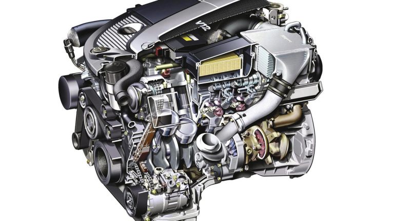
The Mercedes-Benz M275 was a 5.5-litre biturbo V12 engine that was first introduced in 2002 in the W221 S 600. Manufactured at Mercedes-Benz’s engine plan in Berlin-Marienfelde, key features of the M275 engine included its:
- Die-cast aluminium crankcase;
- Aluminium alloy cylinder head with die-cast magnesium cover;
- Forged crankshaft, connecting rods and pistons;
- Single overhead camshaft per cylinder bank;
- Roller-type cam followers actuating two intake valves and one exhaust valve per cylinder;
- Two turbochargers with air/water intercooling and wastegate valve;
- Intake manifold injection; and,
- Two spark plugs per cylinder (i.e. twin spark ignition).
The standard M275 engine had an 82.0 mm bore and 87.0 mm stroke for a capacity of 5513 cc. In addition to its aluminium alloy block and cylinder head, the M275 engine had twin turbochargers, manifold fuel injection, an intercooler, a single overhead camshaft per cylinder bank, three valves per cylinder (two intake and one exhaust) that were actuated by aluminium roller rocker arms and two spark plugs per cylinder (i.e. twin spark ignition).
Peak boost pressure for the M275.950 engine was 1.9 bar and this enabled it to produce peak power and torque outputs of 368 kW at 5000 rpm and 800 Nm at 1800-3500 rpm. However, 500 Nm was produced at 1000 rpm and 600 Nm at 1500 rpm. Furthermore, the M275 engine weighed 270 kg, around 50 kg heavier than the M137 V12 engine which it replaced.
The M275 engine was superseded by M279 engine in 2012.
M285 engine
The Maybach W240 57 and V240 62 were powered by the M285 engine. The higher outputs for the M285 engine were achieved by using a different performance map for the motor electronic control module.
M275 AMG engine
For the AMG version of the M275 – the M275 E 60 AL, also known as the ‘M275 AMG’ – cylinder bores increased to 82.6 mm and stroke to 93.0 mm for a capacity of 5980 cc. The M275 AMG engine also had air-to-liquid intercoolers and the turbochargers provided peak boost pressure of 1.52 bar (22.1 psi).
For the M275 AMG engine, peak torque was electronically limited to 1000 Nm to avoid transmission damage. According to Mercedes-Benz, the engine would have otherwise been capable of producing in excess of 1100 Nm.
[su_table responsive=”yes”]
| M275.981 AMG | M275.950 | M285.950 | M137.970 | |
|---|---|---|---|---|
| Configuration | 60° V12 | 60° V12 | 60° V12 | 60° V12 |
| Displacement | 5980 cc | 5513 cc | 5513 cc | 5786 cc |
| Bore | 82.6 mm | 82.0 mm | 82.0 mm | 84.0 mm |
| Stroke | 93.0 mm | 87.0 mm | 87.0 mm | 87.0 mm |
| Cylinder bore spacing | 90.0 mm | 90.0 mm | 90.0 mm | 90.0 mm |
| Cylinder wall thickness | N/A | 8 mm | 8 mm | 6 mm |
| Valves per cylinder | 3 | 3 | 3 | 3 |
| Spark plugs per cylinder | 2 | 2 | 2 | 2 |
| Induction | Biturbo | Biturbo | Biturbo | Naturally aspirated |
| Peak boost | 1.5 bar | 1.9 bar | 1.9 bar | N/A |
| Power | 450 kW at 4800-5100 rpm | 368 kW at 5000 rpm | 405 kW at 5250 rpm | 270 kW at 5500 rpm |
| Torque | 1000 Nm at 2000-4000 rpm | 800 Nm at 1800-3500 rpm | 900 Nm at 2300-3000 rpm | 530 Nm at 4100 rpm |
[/su_table]
Crankcase
The M275 engine had a die-cast aluminium crankcase 82.0 mm bores – spaced at 90 mm intervals – and an 87.0 mm stroke for a capacity of 5513 cc. The M275 crankcase had a two-piece bedplate design, with large gray cast iron inserts in the main bearings of the lower crankcase reduce noise.
Within the cylinder bores, the M275 engine had Silitec (aluminium-silicon) cylinder liners that had a wall thickness of 2.5 mm. Compared to the M137, the walls between the cylinders of the upper crankcase were widened by 2 mm to 8 mm and three water cooling bores were integrated into the cylinder walls – this was necessary due to the forced induction of the M275 engine.
The crankcase of the M275 engine was ventilated via a centrifugal oil separator that was driven by the left camshaft. Vapours from the crankcase which contained oil mist would enter the centrifuge and rotate so that the oil particles would separate from the gases and drip back into the crankcase. The cleaned air would then flow into the pressure regulator and – depending on the operating state of the engine – would be fed directly into the charge air manifold or into the intake line of the left turbocharger.
Crankshaft, connecting rods and pistons
The M275 engine had:
- A forged steel crankshaft which had precision-turned counterweights;
- Cracked and forged steel alloy connecting rods that were 142.3 mm long; and,
- Forged aluminium alloy pistons that were galvanically coated with iron.
Cylinder head
The M275 engine had an aluminium cylinder head with a single overhead camshaft (SOHC) per cylinder bank. The camshafts were driven by a twin roller chain and had hydraulic tensioners.
For each cylinder, the M275 engine had two intake valves and a single hollow-stemmed exhaust valve that was filled with sodium for heat dissipation. The valves were actuated by roller-type cam followers with hydraulic valve clearance compensation. The valve springs were identical on the intake and exhaust sides, and specially designed to cope with the higher exhaust back pressure prevalent in turbocharged engines.
The M275 engine did not have camshaft adjustment since, according to Mercedes-Benz, the engine’s torque output rendered camshaft adjustment ‘superfluous’.
Turbocharging
Each of the cylinder banks of the M275 engine had a liquid-cooled turbocharger. The turbochargers were made of cast steel and the turbine housings were integrated into the three-piece exhaust manifolds. The turbochargers drew in fresh air via the air filters at the compressor intakes and directed it via compressor outlets into the charge air pipes upstream of the charge air coolers.
To cool the turbochargers, coolant would flow to each of the turbocharger bearing housings via a different connection in the cylinder crankcase and pass through the bearing housings from bottom to top. The cooling streams would then be fed back into the main cooling circuit at the right cylinder head. The flow of coolant through the turbochargers was assisted by the pressure differential in the water jacket – this is an example of the thermosiphon principle whereby the difference in density between warm and cold water causes the warm (i.e. lighter) water to rise upwards.
For each turbocharger, the turbine wheel and compressor impeller were supplied with oil via the engine’s oil circuit. The lubricating oil was taken from the main oil duct of the cylinder crankcase and would flow through the bearing housing in the opposite direction to the coolant. The lubricating oil would then be is extracted individually for each turbocharger from the engine oil pump.
For the M275.950 engine, the exhaust gas turbochargers were produced by the 3K-Warner company (designation K24.2-2472 DXB 6.8.1). These turbochargers generated boost pressure from around 1500 rpm, with maximum boost pressure of 1.9 bar reached at approximately 2000 rpm; the maximum speed of the turbochargers was 160,000 rpm.
Boost pressure control
To regulate boost pressure, the exhaust streams that drove the turbine wheels could be diverted through bypasses by opening wastegate flaps; these flaps were opened by the vacuum cells via a control rod.
Charge air coolers
The M275 engine had one charge air cooler for each cylinder bank and both charge air coolers were connected to a separate low-temperature cooling circuit which included a low-temperature cooler, expansion reservoir and charge air cooler circulation pump. The heated charge air would transfer its heat to the coolant which flowed through the charge air cooler, acting as an air/water heat exchanger. The coolant, in turn, would transfer the absorbed heat to the ambient air in the low-temperature cooler.
Ignition
The M275 engine had two spark plugs per cylinder and the ignition coils were located in the upper section of each spark plug connector. As such, the engine has 24 ignition circuits. To prevent knock (i.e. uncontrolled detonation), the M275 engine had four knock sensors.
[su_table responsive=”yes”]
| Engine | Capacity | Peak power | Peak torque | Model | Years |
|---|---|---|---|---|---|
| M275 E 55 AL | 5513 cc | 368 kW at 5000 rpm | 800 Nm at 1800-3500 rpm | C215 CL 600 | 2002-06 |
| W220 S 600 | 2002-05 | ||||
| R230 SL 600 | 2002-06 | ||||
| 380 kW at 5000 rpm | 830 Nm at 1800-3500 rpm | C216 CL 600 | 2006-13 | ||
| W221 S 600 | 2006-13 | ||||
| R230 SL 600 | 2006-11 | ||||
| M275 E 60 AL | 5980 cc | 450 kW at 4800-5100 rpm | 1000 Nm at 2000-4000 rpm | C215 CL 65 AMG | 2003-06 |
| C216 CL 65 AMG | 2006-10 | ||||
| V220 S 65 AMG | 2004-05 | ||||
| V221 S 65 AMG | 2006-10 | ||||
| R230 SL 65 AMG | 2005-13 | ||||
| 463 kW at 4800 rpm | 1000 Nm at 2300-4300 rpm | C216 CL 65 AMG | 2010-13 | ||
| V221 S 65 AMG | 2010-13 | ||||
| 493 kW at 5400 rpm | 1000 Nm at 2200-4200 rpm | R230 SL 65 AMG Black Series | 2008-10 |
[/su_table]
Mercedes-Benz M275 AMG V12 engine


