[su_image_carousel source=”media: 51148,51149,51150,51151,51152,51153,51154,51155,51156,51157″]
Introduction
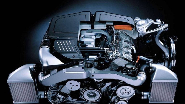
Audi’s BCY engine was a 4.2-litre biturbo V8 engine which was introduced in the Audi C5 RS6. Based on the AQJ/ANK engine in the Audi C5 S6, key features of the BCY engine included its:
- Cast aluminium alloy block with a 90-degree ‘V’ angle;
- Die-forged steel crankshaft;
- Aluminium-silicon (‘Alusil’) cylinder head;
- Double overhead camshafts driven by a toothed belt and simplex chain;
- Five valves per cylinder actuated by roller-bearing rocker arms;
- Torque was limited to protect the ZF 5HP24A transmission;
- Parallel Borg Warner K04 turbochargers which provided peak charge pressure of 0.8 bar;
- Two side-mounted intercoolers;
- Compression ratio of 9.8:1;
- Electronic multi-point sequential fuel injection;
- Bosch Motronic ME 7.1.1;
- Maximum engine speed of 6700 rpm; and,
- Euro 3 emissions compliance.
The BCY engine weighed 230 kg.
[su_table responsive=”yes”]
| Model | Engine | Trans. | Peak power | Peak torque |
|---|---|---|---|---|
| Audi C5 RS6 | 4.2-litre BCY biturbo petrol V8 | 5sp auto | 331kW at 5700-6400rpm | 560Nm at 1950-5600rpm |
[/su_table]
Block
The BCY engine had a cast aluminium alloy block with 84.5 mm bores and a 93.0 mm stroke for a capacity of 4172 cc. The die-forged steel crankshaft was supported by five main bearings; for the BCY engine, the crankshaft was modified in the flange area and fitted with a doubly reinforced ten-hole flange drive plate.
The BCY engine had forged connecting rods and cast aluminium alloy pistons which had a Ferrostan II coating for the piston skirts.
Crankcase breather
The BCY engine had a crankcase breather which consisted of a pressure limiting valve, a non-return valve and associated hoses. Specifically,
- The oil vapours and ‘blow-by’ gases from the cylinder heads and the crankcase converged in the distributor piece; and,
- The pressure limiting valve and the non-return valve controlled the return of these vapours and gases to the engine, depending on intake manifold pressure
Cylinder head
The BCY engine had an aluminium-silicon (‘Alusil’) cylinder head that was mounted on a four-layer gasket; the gaskets were made from beaded, elastomer-coated spring steel layers. Like the ASJ/AZR engine for the Audi B5 RS4, it is understood that Cosworth Technologies were involved for the production of precision sand-cast parts.
Coolant flow direction for the BCY engine was the same as Audi’s concurrent V6 and V8 engines. As such, coolant flowed from the cylinder heads, merged in the rear coolant pipe and then flowed to the cooler. For the BCY engine, however, the water jacket was revised to improve cooling in the areas around the combustion chambers and exhaust ports; this also required changes to coolant passages in the head gasket.
The double overhead camshafts were driven by a toothed belt and simplex chain and used roller-bearing rocker arms to actuate the five valves per cylinder (three intake and two exhaust). The roller rockers were made of die-cast aluminium and, compared to the mechanical bucket tappets, reduced frictional losses in the valvegear. The rockers were supported by a spindle shaft which was also used to supply oil to the bearings and the hydraulic valve lifters. Valve actuation, however, differed between intake and exhaust valves:
- The two exhaust valves per cylinder were actuated by a twin roller rocker that, in turn, was actuated by a single cam by means of a roller located between the rocker arms; and,
- The three intake valves per cylinder were actuated by a triple roller rocker that was actuated by a double cam by means of two rollers between the rocker arms. For uniform compression between the two cams and rollers of the roller rockers, the spindle shaft of the inlet roller rocker had a convex shape to prevent the roller rockers from tilting.
For the BCY engine, the diameter of the exhaust valves was reduced to 27 mm, while the stems were filled with sodium to improve heat dissipation. Furthermore, the 4.2-litre BCY engine had variable intake camshaft timing.
Intake manifold
The BCY engine had a fresh air intake system with two branches to reduce pressure losses, with the branches joined upstream of the throttle valve. For the BCY engine, however, two large air cleaner elements were added due to the increased air requirements of the turbocharged engine. After passing through the mass air flow sensors, the air was routed through a piping system to the water-cooled turbochargers.
The BCY engine did not have a variable intake manifold (VIM).
Borg Warner K04 Turbochargers
The BCY engine had two water-cooled KKK/Borg Warner K04 turbochargers, one for each cylinder bank, that were attached to the exhaust manifold using the ‘stud and nut’ method. For the BCY engine, maximum relative charge (or boost) pressure was 0.8 bar (11.6 psi); to protect the ZF 5HP24A transmission, torque output was regulated. The part numbers for the turbochargers was as follows:
- OEM part no: 077145703P (left); and,
- OEM part no: 077145704K (right).
Charge pressure control
The air mass required to develop a specific level of torque was determined by an air mass calculation and produced by controlling the charge pressure as required. The Bosch Motronic ME 7.1 engine management system regulated charge pressure of both turbochargers via the solenoid valve for charge pressure control. The purpose of charge pressure control was to prevent an excessively high charge pressure from accumulating in the intake system.
To avoid pumping the turbochargers when a sudden transition was made from high load to over-run, two divert air valves were used. The Bosch Motronic ME 7.1 engine management system could activate the divert air valves via an electrical changeover valve.
Charge pressure cooler (intercooler)
The charge air coolers received cooling air from air intakes in the bumper and air vents in the wheel housing liners. The charge air coolers increased the density of the intake air for greater efficiency and the lower temperature also suppressed knocking. The compressed air streams then converged upstream of the throttle valve control part and were distributed to the individual cylinders in the intake manifold.
Injection and ignition
The BCY engine had two fuel pumps connected in series:
- A pre-supply pump located in the fuel tank; and,
- A transfer fuel pump fitted to the tank as an external unit.
From the common fuel rail, the BCY engine had electronically-controlled multi-point sequential fuel injection via eight injectors that were positioned in the intake manifold. For ignition, the BCY engine had eight individual single-spark ignition coils and NGK longlife spark plugs.
The injection and ignition process was controlled by the Bosch Motronic ME 7.1 engine management system which used a hot film air mass meter to measure intake air volume, three knock sensors and two heated oxygen sensors for adaptive lambda control.
The BCY engine had a compression ratio of 9.8:1 and 1-5-4-8-6-3-7-2 firing order.
Exhaust
The BCY engine had two air-gap insulated exhaust manifolds that connected to a dual-branch exhaust system with large-section pipes to minimise back-pressure. For emissions control, the BCY engine had two under-bonnet primary catalytic converters and two under-floor main catalytic converters; all converters used a metal substrate.
Secondary air injection system
The BCY engine had a secondary air injection system so that the catalytic converters reached their operating temperature faster. In this process, the fuel mixture was enriched to produce a higher percentage of unburnt hydrocarbons in the exhaust gas. The secondary air injection – located downstream of the exhaust valves – then enriched the exhaust gases with oxygen, causing oxidation (i.e. after-burning) of the hydrocarbons and carbon monoxide.


